
Contents
Project aims
”Everyone knows what an emotion is, until asked to give a definition”

                                                                Beverly Fehr and James Russell
 Research on Human-Computer-Interfaces has recently begun to take into account the affective state of the user. By appropriately reacting to the affective user state, interfaces could not only become more pleasant or entertaining, but also more effective or safer. It is known that affective states have bodily correlates, and thus physiological signals could provide the necessary information for acquiring the affective user state. In contrast to other sources of information about the affective user state such as speech or facial expression, most physiological signals are not under voluntary control, and thus cannot be masked up to the same extent. Furthermore, it can be presumed that the signs of affective states in physiological signals are less dependent on individual and contextual factors: this is because the signals correspond to internal physiology, largely related to the autonomous nervous and limbic systems, rather than to external expressions that can be manipulated easily. Recently, the issue of emotion regulation drew interests from several fields including neuroscience, psychology, education, computer science, etc. Possible applications are e-learningin, human computer interaction, development of communicative technologies for use by people with autism, car infotainment system, lie detection tests, cognitive workload, multimodal user interfaces MMUI (allow users to control computers using speech and gesture), etc.
The project is aimed at developing a device, connected to a PC, to acquire biological signals (such as GSR, BVP, Temperature and Head orientation) in a way that is less invasive for the subject. The term invasive is related to how much the sensors we use compromise the normal interaction between subject and machine. Through these biological signal the PC is able o understand emotion in people who wear the device.
An affective device should be weared easily, should not have cables and should acquire as much sensors as possible. We relax some constraint on the quality of signal but we add constraint on way they are acquired(i.e. the subject can put it on easily, the usual movements are not influenced..). The aim of the resulting device is not to replace the standard medical devices usually used to acquire that signals, but is to be much more suitable for industrial application in which the medical requirement are replaced by invasivity requirement.
It is composed by:
- Low power, high efficiency, battery powered design
- Wireless comunication with a PC
- Blood Volume Pressure Sensor (Preliminary release by Mattia Colombo)
- Galvanic Skin Response Sensor (Preliminary release by Sala Mirko e Alessia Cornaggia)
- Temperature Sensor
- 3 Way Accelerometer
- Possibility of further extension
GSR (or EDR or EDA)
An often misunderstood and difficult technique, GSR (also known as the electrodermal response EDR or electrodermal activity EDA) has gone through many phases of interest and rejection since the early 1900’s and is very popular in psychophysiological studies since Carl Jung and his students (1907) described it as a mean to enter the “sea of the unconscious” because “every stimulus accompanied by an emotion produced a deviation of the galvanometer” directly proportional to the strength of the emotion aroused. It has been used in important research on anxiety and stress levels (Fenz & Epstein, ‘ 67); and it has been a part of lie detection (Raskin, ‘ 73). Controversy has centered around the technique, underlying mechanisms, and the meaning of the responses obtained from the skin. There has been a long history of electrodermal activity research, even if most investigators accept the phenomenon without understanding exactly what it means (Hume, ‘ 76). The resistance of the skin is usually large, approximately 1M; however, momentary changes in the level of the sweat gland activity causes changes in resistance (up to approximately 950K). Physiology, the GSR reflescts sweat gland activity and changes in the sympathetic nervous system and measurement variables. The activity of the sweat glands in response to sympathetic nervous stimulation ( Increased sympathetic activation ) results in an increase in the level of conductance. There ia a relationship between sympathetic activity and emotional arousal, although one cannot identify the specific emotion being elicited. Basically there are two techniques in the history of Electrodermal measurement. In one a current is passed thru the skin and the the resistance to passage is measured; in the other no current is used externally and the skin itself is the source of electrical activity. By applying a conventional 0.5 Volts across the skin and measuring changes in the corresponding conductance, the emotional state of the subject can be inferred. In general, the electrodes used are of the Ag/AgCl type which are recessed from the skin and require the use of a suitable electrode paste. It is important to note, however, that fluctuations in skin conductivity are resultant of many types of arousal. By observing only these changes, it is impossible to deduce without prior knowledge whether the subject has become happy, startled, physically active, etcetera. EDA consists of two components: tonic and phasic. The tonic component is a low frequency baseline conductivity level, which can oscillate over the course of days. The phasic component rides on top of the tonic component, exhibits more rapid fluctuations, and generally increases when a person is aroused. Problematically, each person has a different tonic conductivity, so in order to infer the arousal level of the subject, the relative changes in EDA must be analyzed over a period of time. Furthermore, skin conductance (measured in units of siemens; formerly mhos) depends on the skin path length between the two electrodes contacts, even for subjects with identical skin conductivity (measured in units of siemens/meter). It is for these reasons that it is crucial to analyze the temporal variations of the EDA signal.
BVP
The cardiovascular system is in charge to keep us alive by maintaining the vital blood flow throughout the body, providing nutrients and oxygen to our cells. The SNS controls this system by shifting the flow in response to exercise, temperature,postural and emotional changes. Blood Volume Pulse (BVP) is the most common measure of vasomotor activity because it reflects the phasic pumping of the heart, the vasodilation of vessels that changes in the amount of acral blood delivered. The Blood Volume Pulse (BVP) waveform is an important indicator of circulatory function that can be obtained noninvasively through a photoplethysmographic transducer (a PPG is often obtained by using a pulse oximeter, Shelley and Shelley, 2001) applied to the finger or the earlobe of human subjects. In particular, this signal may be useful in determining the degree of cardiovascular change undergone by a subject through an exercise session.
Principles of photoplethysmographic Technology:
The principle of photoplethysmographic (That is the same of pulse oximetry) is based on the red and infrared light absorption characteristics of oxygenated and deoxygenated hemoglobin. Oxygenated hemoglobin absorbs more infrared light and allows more red light to pass through. Deoxygenated (or reduced) hemoglobin absorbs more red light and allows more infrared light to pass through. Red light is in the 600-750 nm wavelength light band. Pulse oximetry uses a light emitter with red and infrared LEDs that shines through a reasonably translucent site with good blood flow. Opposite the emitter is a photodetector that receives the light that passes through the measuring site. There are two methods of sending light through the measuring site: transmission and reflectance. In the transmission the emitter and photodetector are opposite of each other with the measuring site in-between. The light can then pass through the site. In the reflectance method, the emitter and photodetector are next to each other on top the measuring site. The light bounces from the emitter to the detector across the site. The transmission method is the most common type used. While pulse oximeters are a commonly used medical device the PPG derived from them is rarely displayed, and is nominally only processed to determine heart rate.
Temperature
The temperatures of peripheral limbs vary as a consequence of changes in blood flow.
Previous work
* Skin galvanic response (Sala Mirko e Alessia Cornaggia[1]) Galvanic skin response (GSR), also known as electrodermal response (EDR), psychogalvanic reflex (PGR), or skin conductance response (SCR), is a method of measuring the electrical resistance of the skin. There is a relationship between sympathetic activity and emotional arousal, although one cannot identify the specific emotion being elicited. The GSR is highly sensitive to emotions in some people. Fear, anger, startle response, orienting response and sexual feelings are all among the emotions which may produce similar GSR responses. Response of the skin to the passage of a small electric current. The ease with which the current flows between two points on the skin can be used to indicate stress. When a person is tense or emotional, the sweat glands become more active, increasing moisture on the skin; this allows the electric current to flow more readily. The response may also be used in relaxation training: information about the galvanic skin response is fed back aurally or visually to the subject who can, with practice, learn to increase or decrease sweating on the skin by learning to relax or tense muscles. We measure the galvanic skin response using two electrodes attached to the skin. The optimal placement is the palm of the hands, but we are experimenting other places like on the forehead. The circuit we are creating is the one below.
Project the device
Re-definition of the complete work
Sensors are an important part of an Affective Computing System because they provide information about the wearer’s physical state or behavior. They can gather data in a continuous way without having to interrupt the user. To define in detail electronic specifications and requirements it’s necessary a preliminary research/study (in literature and web) about state of art of sensor type used to monitor each type of biological signals we are interested about. In this way it’s possible both understand problematics related to interaction between biological and electonical worlds and improve or re-desig existing prototype.
About Sensors:
BVP will be acquire by an IR transmitter-receiver measuring light reflected from skin (photoplethysmography). Particular attention will be put on position, geometry and power absorption of this stage.
GSR will be acquiret by a couple of electrodes forcing a low current (or voltage) and reading voltage (or current) through electrodes. Particular attention will be put on electrodes position and material. In addition is possible to foresee some problems in amplifier stage due to large range of skin resistance. Problem consist in chosing a correct amplification to overwork ADC full scale with a signal affected by little variation but huge possible range.
Temperature will be acquired by thermocouple or PTC/NTC. Slowly variable signal, possible problems with noise due to resolution required.
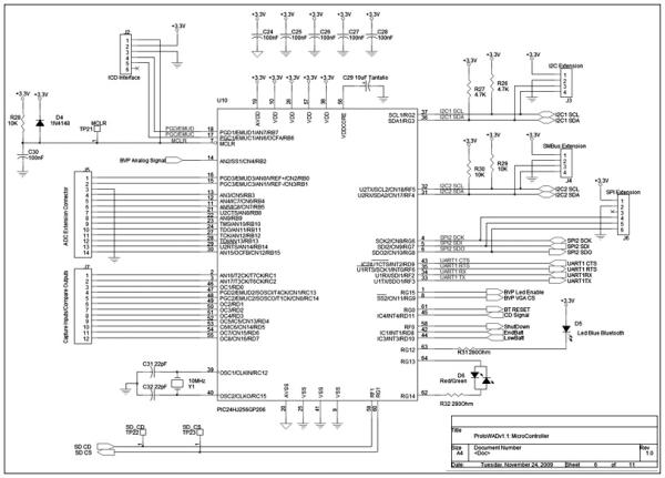
Head orientation will be acquired by an accelerometer and a gyroscope, problably integrated in the same chip. Two possibilities: analog output (need to digitalize up to six line) or digital output (like displaied in schematic block diagram).
This was the preliminary simplified schematic block diagram of the complete instrumentation setup:
NOTE:

* In schematic is not present Power Supply Module: it will be based on a rechargeable Li-ion
battery. It must satisfy requirements of high efficiency, logn life and low weight.

* ADC and Microcontroller could be unified using a microcontroller with internal ADC and
internal or external multiplexer to select lines.

* Wireless section could be implemeted in Bluetooth (instead of using a XBee module like in
preliminary release) due to it's diffusion in cellular phones, notebooks, MP3 reader...
without necessity of external modules.
It was based on a theoretical approach to any single part. Any sensing device was designed in “conventional” way founded on analog electronic (a bridge with a NTC resisistance as sensing element, discrete IR led and some photodiode around to capture the most reflefted light as possible, GSR electrodes on the gain arm of a non-inverting amplifier…). Unfortunatly a deep analysis on signal physiology, signal transduction, noise vs required accurancy, forced us to a completely different approach implementing everywhere possible a digital interface.
 Sensors Design
BVP
Discrete IR leds and phototransistor, used in the first realize (see fig.), had been replaced first with a single led and one or more photodiodes to optimize power consumption in case of non-planar sensor positioning. Subsequently an integrated Reflective Object Sensor was introduced, with benefits about space saving, transmitter-receiver matching and power consumption. To ensure light power stability, led is powered through a linear led drive LDO (Low Drop-Out). The choise of linear LDO is necessary to ensure no noise or spikes would be generated by charge pump systems or boost converters. In addition, the linear drive utilized requires only one external resitor to set led current and a decoupling capacitor, reducing part counts and board space occupation. The couple factor of the reflex sensors is relatively small, even in the case of good reflecting surfaces. Therefore an additional amplifier is necessary at the sensor output: classic trans-impedance amplifier used with photo-diodes and photo-transistors was introduced. This circuit features an output voltage that is a linear function of the light level on the photo-transistor. The gain is set by the feedback resistor which could be in the millions of ohms. Linear operation is achieved by operating the photo device with a fixed voltage drop across it. Trans-impedance amplifier is followed by an active fourth order band-pass filter (0.5Hz-5Hz): it’s composed cascading two second order bandpass cells. In first project session only a single cell was used, but a deeper study combined with previous experiences suggests to use a 4th order filter to reduce 50Hz interference (50Hz interference produced by mains is placed only a decade after the filter pole). Filter is followed by a VGA (Variable Gain Amplifier) digitally controlled through I2C Bus that allows to optimize dinamically ADC input signal amplitude directly during acquisition session, obtaining the best performance from ADC. The resulting circuit is quite compact (led drive, reflective sensor, trans-impedence amplifier, active filter and variable-gain amplifier), doesn’t require much power and represents a good mix between analog and digital approach: analog front-end with acquisition and first conditioning, and at the chain-end a digital controlled amplifier to ensure flexibility.
For more detail: Talk:Wireless Affective Devices
