Introduction
By combining a PIC microcontroller or Basic Stamp II with a few passive components it is not difficult to construct your own knob box, trigger box, or other MIDI input device. A knowledge of electronics may be required for interfacing to some sensors. Both the Stamp and PIC provide an economical (under US$100) entry point into the world of alternative MIDI controllers.
This page was created to provide a starting point for people interested in building their own MIDI control devices using Microchip PIC microcontrollers or Parallax Basic Stamps. If you have any comments or suggestions please feel free to email me.
 Basic Stamps and PICs
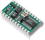
A Basic Stamp consists of a tiny circuit board on which is soldered a PIC CPU, a timing crystal, and some EEPROM memory for program storage. It provides 16 bidirectional data (digital input/output) pins, which can be interfaced to potentiometers, a simple MIDI output circuit, A/D converters, etc. As its name suggests the Basic Stamp executes code written in BASIC, which is downloaded onto the stamp using a serial interface. Parallax, Inc. manufacture a number of different Basic Stamp models, the Basic Stamp II and IIsx are generally considered fast enough for MIDI transmission applications, but neither supports MIDI input satisfactorily.
Microchip Technology Inc. manufacture a large range of PIC microcontrollers. For small projects the PIC16F84 is a common choice as it is cheap and uses reprogrammable flash ROM for program storage. The PIC16F84 chip contains 1k words of program flash ROM, 68 bytes of RAM and 64 bytes of EEPROM for persistent data storage. The PIC16F84 has 13 bidirectional data pins which can be used in a similar fashion to those on the Basic Stamp. PIC chips are programmed in assembly language which is then stored onto the chip using a special programmer. For PC users a parallel port based programmer for the PIC16F84 can be built for around $30. Both Microchip and Parallax distribute free PIC assembler software for the PC.
The general opinion is that the Basic Stamp II is a better starting point for people with little or no programming or electronics experience, as using a PIC directly requires you to learn PIC assembly language which can be tedious if you’re not into that kind of thing. If you’re a programmer or you’re looking at using more than one unit the PIC16F84 is good choice as it’s cheap and can often be made to do things faster than the Basic Stamp. You can assemble a programmer, a few PIC chips and some power supply circuitry for less than the cost of a Basic Stamp II.
See Peter H. Anderson’s article Working with Stamps and PICs for an extensive discussion of the relative merits of PICs and Basic Stamps.
Interfacing to MIDI
For both the Basic Stamp II and medium range PIC chips, MIDI (i.e. serial) output is implemented in software by manipulating the state of a data pin. On the Basic Stamp this is achieved using the SEROUT command, on the PIC you have to roll your own MIDI output routine – this can be tricky as the serial timing is determined by the number of instructions executed and the clock speed of the PIC, however there are plety of examples available on the web to get you started.
Neither the medium range PICs (such as the PIC16F84) nor the Basic Stamp (any model) are particularly suited to simultaneous MIDI reception and transmision as they do not support buffered serial communications. On the Basic Stamp II, any MIDI coming in while the Stamp is processing will be lost. On a PIC, code must be carefully designed to interleave serial reads and other processing at the sub-MIDI bit level to avoid loss of data.
MIDI input without output is possible on a PIC, but is not described here – see the links section for some examples. Implementing simultaneous MIDI in and out, or soft thru / merge is impossible using a Basic Stamp II. It is difficult to implement on the PIC16F84 and leaves little room for other processing to be performed. A suggested solution is to use two PICs – one for input and one for output, or to use a more expensive PIC such as the PIC16C7x which has an on-chip UART.
MIDI output
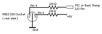
Wiring up a PIC or Basic Stamp for MIDI output couldn’t be simpler:
- Connect pin 4 of the MIDI connector to the desired output pin of the PIC or Basic Stamp via a 220 Ohm resistor
- Connect pin 5 of the MIDI connector to the +5V via a 220 Ohm resistor
- Connect pin 2 of the MIDI connector to ground
Important Note! A couple of people have written to me suggesting that the pins 4 and 5 on the MIDI output wiring diagram are reversed. I havn’t verified whether this is true or not. You may need to experiment by swapping the connections if it doesn’t work.
See either David B. Thomas’ MIDI Sender (Parallax assembler) or my midisend (Microchip assember) progam for an example of sending MIDI using a PIC chip. For the Basic Stamp II see Jeff Mann’s MIDI out program for BASIC Stamp II.
If you’re looking for information about MIDI, visit The MIDI Technical Fanatic’s Brainwashing Center. The MIDI electrical specification diagram along with other useful information is available from the MIDI Manufacturers Association website.
 Interfacing to variable resistances
Although this section discusses potentiometers (as used with Knobs, Faders and Joysticks), the information can also be appied to other variable resistance devices such as Light Dependent Resistors (LDRs) or Forces Sensing Resistors (FSRs).
The dual input / output nature of PIC and Basic Stamp data pins allows a simple circuit to be constructed that can measure the value of a potentiometer. There are two different circuits commonly used for performing this measurement: the first was used in conjunction with the Basic Stamp I POT command and is useful on the PIC as source code to drive it is freely available (this is the version described below). The Basic Stamp II replaced the POT command with the RCTIME command which requires a different circuit – see the Stamp II manual for details or John Radenberg’s Basic Stamp DIY knob box page for a functioning example.
The POT method
A measurement is made by first charging the capacitor (making the data pin output a high), then setting the pin to input and slowly discharging it (by toggling the pin between input and output). The time taken for the pin to go low corresponds to the time it takes for the capacitor to discharge which is related to the resistance of the potentiometer.
For more detail: DIY MIDI controllers using PIC microcontrollers and Basic Stamps