Summary of Sonar range finder using PIC16F88 Microcontroller
This article describes a PIC-based ultrasonic range finder using a 40kHz transducer and a microcontroller. It explains the echo-ranging principle, calculating distance via sound speed and round-trip time. The system employs five transistors for amplification, a comparator for threshold detection, and the PIC's CCP module to measure timing accurately. The design uses an internal 4MHz oscillator to save I/O pins and allows code modification for different frequencies or environments.
Parts used in the PIC Sonar Range Finder:
- PIC Microcontroller
- Five standard transistors
- Comparator
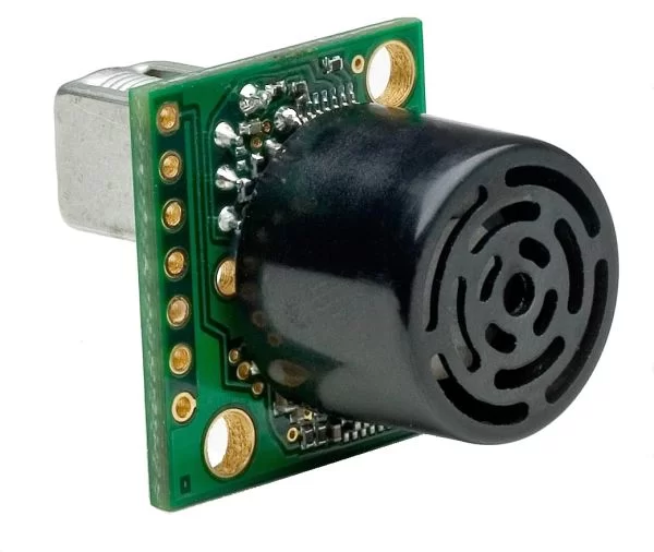
- 40kHz Ultrasonic Transducers
- Three transistor amplifier
- Peak detector
- CCP module (Capture mode)
- Timer 1
The PIC sonar range finder works by transmitting a short pulse of sound at a frequency inaudible to the ear (ultrasonic sound or ultrasound).
Afterwards the microcontroller listens for an echo.
The time from transmission to echo reception lets you calculate the distance from the object.
PIC Sonar Specification
| Range | ~5cm – 300cm |
| Accuracy | +/-3cm |
| Transducer frequency | 40kHz |
| nternal oscillator frequency | 4MHz |
The project uses 5 standard transistors to receive and transmit the ultrasound and a comparator to set the threshold echo detection level – so there are no special components other than the microcontroller.
The ultrasonic transducers are standard 40kHz types.
Note that the internal oscillator of the PIC micro is used and this saves two pins – that can be used for normal I/O,
You can recompile the pic sonar project files if you want examine code operation (using the built in simulator) or change the source code. Note the hex file is contained in the download.
How the PIC Sonar rangefinder works
Since the speed of sound is constant through air measuring the echo reflection time lets you calculate the distance to the object using the DST equation :
Distance = (s * t)/2 (in metres)
You need to divide by 2 as the distance is the round trip distance i.e. from transmitter to object and back again.
Where:
| s [m/s] | the speed of sound in air |
| t [s] | the round trip echo time. |
Some delay times:
| Round trip echo time | Distance |
| t = 588us | 10cm |
| t = 5.8ms | 1m |
Note: The speed of sound in air is more or less constant at 330m/s (@ 0ºC) – it varies mainly with temperature (~340m/s @ 20ºC). In this project I am using a value of 340m/s i.e. it is assumed that the project is used indoors. You can change it to whatever you like by modifying the code.
You can get ultrasonic transducers optimized for 25kHz, 32kHz, 40kHz or wide bandwidth transducers. This project uses a 40kHz transducer but it will still work with the others if you make simple changes to the software (where it generates the 40kz signal). The receiver and generator circuits will work as they are.
Note: If you use a different transducer you must change the software to generate the correct frequency for the transducer as they only work at their specific operating frequency.
The 40kz signal is easily generated by the microcontroller but detection requires a sensitive amplifier. I have used a three transistor amplifier for the receiver.
This is followed by a peak detector and comparator which sets the sensitivity threshold so that false reflections (weaker signals) are ignored.
CCP – Capture mode
This project makes use of the CCP module (in its capture mode) to accurately measure the signal reception time at the CCP port pin. When a signal triggers the CCP module the value of timer 1 is stored in a CCP register (or captured).
If you store the value of timer 1 and then enable the CCP after transmitting an ultrasound pulse the CCP will trigger when the comparator activates i.e. as soon as an ultrasonic echo is received.
Subtracting the stored value from the CCP register value gives the time delay in machine cycles. Since the project uses a 4MHz main clock then the time delay will be measured in micro-seconds.
For more detail: Sonar range finder using PIC16F88 Microcontroller
- How does the project calculate distance?
It calculates distance by measuring the time from pulse transmission to echo reception and applying the formula Distance = (s * t)/2. - Can this project work with transducers other than 40kHz?
Yes, it will work with other frequencies like 25kHz or 32kHz if you modify the software to generate the correct signal frequency. - What is the accuracy of the range finder?
The accuracy is specified as plus or minus 3cm. - Does the project use external oscillators?
No, the project uses the internal oscillator of the PIC microcontroller which saves two pins for normal I/O. - How is the echo signal detected?
A sensitive three-transistor amplifier followed by a peak detector and comparator sets the sensitivity threshold to ignore false reflections. - What role does the CCP module play?
The CCP module in capture mode accurately measures the signal reception time by storing the Timer 1 value when the comparator activates. - What speed of sound is assumed in the calculations?
The project assumes a speed of sound of 340m/s, which corresponds to indoor conditions at approximately 20 degrees Celsius. - Is the source code available for modification?
Yes, users can recompile the project files to examine code operation or change the source code.