
Summary of Smart doorbell System
This article describes a PIC16F84A microcontroller-based doorbell system for industrial use. It features a 10-second horn, resettable light output, secret/emergency codes via button presses, and a temporary mute mode. The circuit uses a UNL2003A driver chip, operates on 12VDC with a 14 MHz crystal, and includes jumper settings for sound duration. Software written in High-Tech C handles interrupts without blocking tasks, managing delays internally.
Parts used in the Microcontroller-Based Doorbell System:
- PIC16F84A microprocessor
- 14 MHz crystal
- UNL2003A IC driver chip
- LED lamp with two decks of LEDs
- Horn
- Push-buttons
- Reset-button
- Jumper SJ1
- Prototype PCB
Introduction
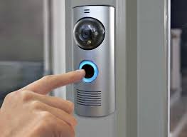
On request I have built a microcontroller-based doorbell system which is being used in an industrial environment. This is the basic function: When you push the bell-button, a horn will sound for about 10 seconds. At the same time a light, which keeps burning until someone pushes a reset-button, will be activated.
 The system has a lot of features:
- There are 2 different lamp outputs: these can be used to control a LED lamp with two different decks of LEDs.
- Possibility to enter a ‘secret’ code: push the bell button 3 times to activate a secret code (the light will now flash).
- Possibility to enter an ’emergency’ code: push the bell button 10 times to activate a secret code (the light will now flash very rapid and the horn will sound for 1 minute).
- Possibility to enable a temporary mute-mode by pressing the reset-button for 5 seconds: now the horn won’t be activated unless someone pushes the secret/emergency code.
- The temporary mute-mode is automatically turned off after 45 minutes. It can also be disabled manually: push the reset button again for 5 seconds.
- During the mute-mode the light flashes once per minute to indicate the mute-mode is active.
- Jumper selection: choose the horn-sounding time (5 seconds/10 seconds).
- The light is turned off after 15 minutes as some sort of overheat protection.
- The PIC is placed into a low-power sleep mode after 15 minutes.
Schematics
Here you can find the schematics for this circuit. I didn’t create a PCB design because it was soldered on a prototype PCB. You can also download the PDF version of this circuit.
This circuit uses a PIC16F84A microprocessor whose frequency is regulated by a 14 MHz crystal. The circuit itself should be powered by a 12VDC voltage. Attention: I didn’t add a protection against reversing the polarity of the inputs.
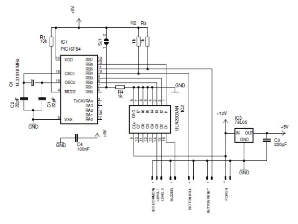 The outputs are controlled by an UNL2003A IC. This is a driver chip that can deliver currents up to 500 mA. According to the datasheet you can put drivers in parallel to increase the output current.
- By setting jumper SJ1 you can make the pin RB1 of the microprocessor HIGH: this will shorten the duration of the horn sounding time from 10 seconds to 5 seconds.
- The push-buttons are connected to the ground: pushing them will make the inputs of the microcontroller low. I did not foresee any circuitry to avoid contact bounce: this is done in the software of the microcontroller.
Software
The software for the PIC is written in High-Tech C (the freeware version that is shipped with Microchip MPLab). You can download it at the bottom of this webpage.
The software is written in a way a certain task doesn’t block the other tasks. Every large delay is split up into tiny delays.
A push on any of the push buttons will cause an interrupt (PortB portchange interrupt). During the execution of the interrupt handler an internal counter is increased. This counter holds the number of times the button was pressed. If you take a look at the source code you will probably notice there is a delay function inside the interrupt handler. I realize this is a big NO-NO as an interrupt handler should finish its task as quickly as possible. But in this particular case I don’t see any harm in delaying the handler.
The microprocessor works with a 14.31818 MHz crystal. This is a little bit high for this kind of application but I had no other crystals at my disposal during the development of the circuit.
Download
You can download the C source for this project here:
| Developed in: | High-Tech C (Microchip) |
| Download type: | Doorbell Source (.C Source) |
| License: | Freeware |
| Size: | 1 kB |
| Source code: | Available |
| MD5 Checksum: | 472bddf9f9cdd3f160ac0ce9bc103411 |
Source: Smart doorbell System
- How does the system activate the emergency code?
Push the bell button 10 times to activate the emergency code. - What happens when the emergency code is activated?
The light flashes very rapidly and the horn sounds for one minute. - Can I change the horn sounding time?
Yes, setting jumper SJ1 shortens the duration from 10 seconds to 5 seconds. - How do I enable the temporary mute-mode?
Press the reset-button for 5 seconds to enable the mute-mode. - When does the temporary mute-mode turn off automatically?
The mute-mode is automatically turned off after 45 minutes. - Does the light stay on indefinitely?
No, the light turns off after 15 minutes as an overheat protection measure. - What voltage should power this circuit?
The circuit should be powered by a 12VDC voltage. - Is contact bounce handled in hardware or software?
Contact bounce is handled in the software of the microcontroller.

