General description
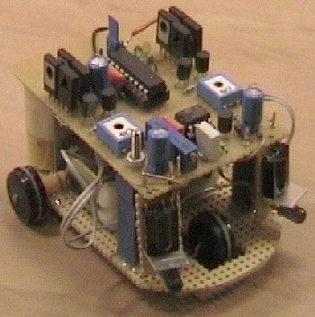
erberes is a small three wheel robot that avoids obstacles which it senses with its active infrared sensors.
Each rear wheel has its own motor, the single front wheel is not powered. The robot steers “like a tank” by rotating the rear wheels in opposite direction.
The sensors are built with infrared LEDs which are running at 36kHz and two 36 kHz remote control receiver modules.
When the 36 kHz infrared light from the LEDs is reflected by an object, one of the receiver modules will be triggered, and the PIC16F84 µController will steer the ROBOT away from the objects by reversing one of the motors.
Two electric toy ducks were sacrificed for this project.
The motors, axes and axe-holders from the toy ducks are glued on a piece of circuit board which acts as a base plate.
The rotation speed of the motors is reduced by the “worm-wheel” of the motor axes which drive the cogs of the wheel axes.
The circuit is built on another piece of circuit board which is identical to the base plate.
The circuit is placed on top of the base plate.
The 3.6 Volt battery pack (from a cordless phone) is also glued to the base plate.
Circuit description
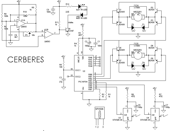
The circuit behind CERBERES can be divided in 3 parts:
- A double motor drive to drive two small electric motors forward / reverse / full stop.
- Two infrared emitters and receivers to sense objects.
- A “brain” which is a PIC 16F84 µController which will drive the motors in reaction to the sensor readings.
The Motor Drive circuit
Both motors are driven by an identical full bridge circuit. The circuit of Motor1 will be used to explain the functionality.
Motor1 is driven by a full bridge built with transistors Q1, Q2, Q3 and Q4.
This full bridge is able to drive the DC motor forward backward and full stop by driving the base
connections of Q1/Q4 and Q2/Q3 as in the table below:
| base Q1/Q4 | base Q2/Q3 | Motor1 action |
| 0 Volt | 0 Volt | STOP |
| 0 Volt | 5 Volt | REVERSE |
| 5 Volt | 0 Volt | FORWARD |
| 5 Volt | 5 Volt | STOP |
The transistors are switched as “emitter followers” which results in a voltage loss of 2 x 0.6 Volts. In this case the
voltage drop was very useful because the the motors from the toy ducks were much too fast at
Cerberes’ battery voltage of 3.6Volts.
The base drive of the transistors limits the output current to about 1-2 Amps typical at 3.6Volts:
The maximum current from the PIC µController is 20mA at 5Volt , the typical Hfe of the BD43 /436 is 130;
this results in a typical maximum current of 20mA x 130 = 2.6 Amps at 5 Volt supply.
When the low operating voltage of 3.6 V is taken into account the max PIC current is even lower: about 1-2 Ampere.
When using other transistors, take into account that a Hfe of 100 or more is required.
The motors from the toy ducks use about 1 Ampere at 2.4 Volts The battery pack has a capacity of about 300mAh
resulting in a typical operating time of about 9 minutes!
In the schematic above, LM393 comparator U1A is used as a 36 kHz oscillator. The frequency is adjusted to exactly 36 kHz
with (multiturn) potentiometer P1.
U1B is a buffer which picks up he oscillator signal without influencung the frequency setting.
The signal is passed on to Q9 which switches two Infrared Leds (e.g. from a remote control) at 36 kHz.
The LM393 is used because it can operate at very low voltages down to 2 Volt , a standard opamp can not be used here!
U3 & U4 are standard SFH506 36kHz infrared receivers which are normally used yo pick up IR signals from
an IR remote control.
For more detail: Small 3-wheel ROBOT with PIC16F84 brain & InfraRed eyes.


