
Summary of Simple Power Guard – PIC12F683
This article describes a simple power guard circuit using a PIC12F683 microcontroller to protect devices from mains transients and voltage spikes. It features a configurable 30-second startup delay, low/high voltage detection via LEDs, and automatic relay control. The system requires calibration of voltage thresholds (200V–260V) by writing specific values to the microcontroller's EEPROM.
Parts used in the Power Guard Circuit:
- PIC12F683 micro-controller
- Green LED
- Yellow LED
- Red LED
- Relay
- 12v step down transformer
- Multimeter
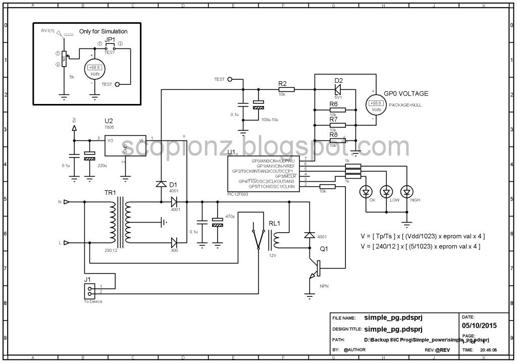
This is a very simple and accurate power guard circuit. This circuit is useful to guard the electronic or electrical devices from mains transients and spikes. Very high spikes can develop at power on due to sparking in the switch and more serious effects occur when power resumes after a power failure due to high magnetic field in the distribution transformer. This will damage your device permanently. To avoid such damages we can use this circuit. 
This circuit used cheap PIC12F683 micro-controller. It controls all the functions of power guard. After power is applied, the green LED starts to blink. This circuit gives a time delay before giving power to the device. Default value is 30 seconds. However, you can change this value. See configuration for more details. After this delay, Green LED turns on permanently. Then Relay activates and connects power to the device.
When the power is abnormal Yellow or Red LED turns on and relay will turn off to protect our device. The Green LED will start to flash again and after delay time it check power status and turn relay on if the voltage is good. Yellow LED indicates low voltage and Red LED indicate high voltage. If all the LEDs are turn on, that indicates firmware error and pleases re-programmed micro-controller.
Configuration and Calibration
For this circuit I used 12v step down transformer. Its output use to sense the power condition. Before using, you need to calibrate this circuit for working correctly. In my project, I choose 240v as normal, 260v as high and 200v as low voltage.
Connect multimeter to GP0 and check voltage. if it exceed 5v immediately turn off power and check the component and connections. (Typical value is 3 – 3.5v)
V = [Tp/12] x [(Vdd/1023) x Eeprom val x 4] Tp = primary voltage
200 = [240/12] x [(5/1023) x Eeprom val x 4]
260 = [240/12] x [(5/1023) x Eeprom val x 4]
Eeprom value for low condition (200v) = 511 (1FF hex)
GP0 voltage = (2v4)
Eeprom value for high condition (260v) = 664 (298 hex)
GP0 voltage = (3v3)
Write those values to Eeprom.
V high = Eeprom (0)*256 + Eeprom (1) – (0x02 and 0x98)
V low = Eeprom (2)*256 + Eeprom (3) – (0x01 and 0xFF)
To change delay time simply changes the value of Eeprom address 4 (Default 0x3C)
Delay time in seconds = value of Eeprom address / 2
0 < value of Eeprom address < 255 (0 < Delay time in seconds < 127)
Minimum delay time is 0 seconds and maximum delay time is 2 minutes
For more detail: Simple Power Guard – PIC12F683
- What is the primary function of this circuit?
To guard electronic or electrical devices from mains transients, spikes, and abnormal voltage conditions. - How long is the default time delay before power is given to the device?
The default value is 30 seconds after power is applied. - Which LED indicates high voltage conditions?
The Red LED indicates high voltage. - What does it mean if all LEDs turn on simultaneously?
It indicates a firmware error and suggests re-programming the micro-controller. - How can you change the delay time in the project?
You simply change the value stored in Eeprom address 4. - What are the calibrated voltage thresholds mentioned in the text?
The project uses 240v as normal, 260v as high, and 200v as low voltage. - How do you determine the maximum delay time possible?
The maximum delay time is 2 minutes, corresponding to a value of 255 at Eeprom address 4. - Why is a multimeter used during the setup process?
It is connected to GP0 to check voltage and ensure it does not exceed 5v before powering on.
