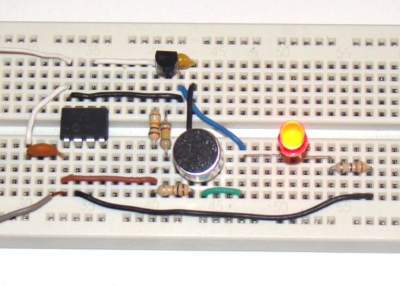
A clap switch is a fun project for beginners. It switches on and off electrical appliances with a sound of clapping hands. Today we will discuss about making a simple clap switch that operates when it detects two clapping sounds in a row. It uses an electret microphone as a transducer for converting a clapping sound into an electrical signal. The microcphone output is amplified by a transistor and is then sent to the PIC12F683 microcontroller which performs an ON/OFF switching action when valid claps are detected.
Theory
The clap switch requires a transducer at the input to convert sound vibrations from clapping hands into electrical energy. An electret microphone or simply mic (OBO-04FN-0B) is used for this purpose. The output from the mic is very low in magnitide and so we need an amplifier circuit to boost the detected sound signal. The following circuit diagram shows the mic along with a single transistor amplifier. When there’s no sound, the collector voltage (Vout) of the transistor, which is saturated, is approximately 0.2V. When the mic detects a clap sound, the voltage across it drops suddenly. Since the condenser mic’s output voltage is coupled to the base of the transistor through capacitor C1, the base-emitter voltage is also lowered and as such the base-emitter junction is less forward biased or cutoff (in case of high clap sound). Therefore, every time a clapping sound is detected, there is a sudden peak arising at the collector voltage.
The following picture shows the peaks in the collector voltage due to multiple clap sounds. You can see the peak voltage can go as high as 4.0V depending on the loudness of the clap. This waveform of the collector voltage is captured using Digilent’s Analog Discovery device.
Now we know how to convert a clap sound into an electrical signal. The next stage is to feed this signal to PIC12F683 microcontroller for switching actions. The PIC12F683 microcontroller has got a built-in comparator module that can be used to compare two analog voltages and obtain a digital indication of their relative magnitudes. The comparator module can operate in eight different modes based on CM2-CM0 bit settings in the CMCON0 register. For our purpose, we will configure it as:
CIN- pin is configured as analog, CIN+ pin is configured as I/O, COUT pin is configured as I/O, Comparator output available internally, CVREF is non-inverting input (see picture below).
We will compare the collector output voltage (Vout) against an internally generated reference voltage. The reference voltage is internally connected to the positive input (CIN+) of the comparator module, while the output voltage from the transducer is fed to the negative input (CIN-) of the comparator. The CIN- pin is multiplexed with GP1 I/O pin of PIC12F683. The magnitude of reference voltage is programmable and controlled through VRCON register. We will set the reference voltage to 0.625V (assuming the supply voltage is 5.0V). So, under normal condition the reference voltage (0.625V) is greater than Vout (=0.2V) and the comparator output (COUT) is high. COUT is accessible internally as well as externally through GP2 I/O pin. When there is a clap sound, COUT will go low. The comparator output logic can be inverted by setting the comparator output inversion (CIN) bit in the CMCON0 register. The PIC12F683 microcontroller can be programmed to take switching actions based on the comparator output.
For more detail: Making a simple clap switch using PIC12F683

