
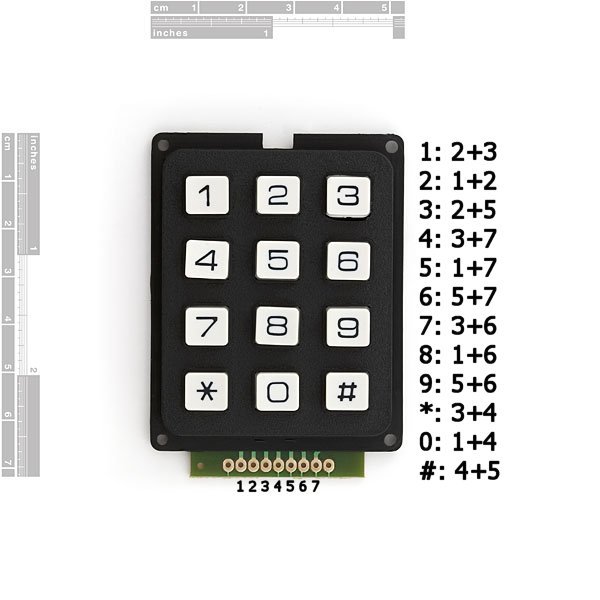
Summary of Simple Button Keypad – Microcontroller
The article describes a simple custom 3x3 button keypad using only microcontroller pins and resistors—no extra hardware. Three pins are driven as outputs (rows) and three as inputs (columns). The firmware scans by setting one output HIGH at a time while keeping others LOW, then reading the three input pins to detect which button in that row is pressed. The process repeats for each output to identify any pressed button.
Parts used in the Simple Button Keypad:
- Microcontroller with at least 6 GPIO pins
- 9 momentary normally-open push buttons
- Resistors (for pull-ups or pull-downs as required)
- Wiring or PCB traces to form a 3x3 matrix
Simple method for creating a custom button keypad that doesn’t require separate hardware. Just your microcontroller buttons a few resistors.
What we have here is 9 buttons and 6 signal lines (3 inputs, 3 outputs). The basic setup is in a grid pattern where the three input lines come down as columns (PIN0, PIN1, and PIN2), and the three output lines come across as rows (PIN3, PIN4, and PIN5).
 Each button is a momentary ON button, normally open. So what will happen is when we press the button it will make a connection between that button’s input and output, other wise there is no connection.
The key here is in the software.
What the software is going to do is sweep between the inputs and outputs, for every combination very fast. I will outline the steps for 1 input, and then it simply repeats the same steps for each other input.
For input on PIN0
— PIN0, 1, 2 defined as outputs
— PIN3, 4, 5 defines as inputs
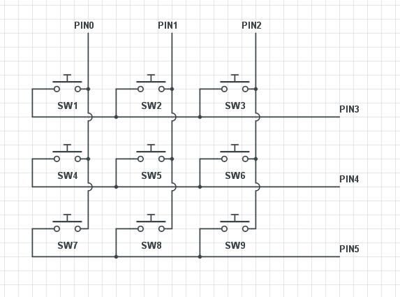 1. Set PIN0, PIN1, AND PIN2 to LOW
2. Set PIN0 to HIGH
3. Check if PIN3 is HIGH or LOW, IF HIGH go to function SW1
4. Check if PIN4 is HIGH or LOW, IF HIGH go to function SW4
5. Check if PIN5 is HIGH or LOW, IF HIGH go to function SW7
6. Set PIN0 to LOW
This will then repeat with the only differences being which input pin is set to HIGH, and the names of the SW functions its going to.
For more detail: Simple Button Keypad – Microcontroller
- How many buttons does the project use?
The project uses 9 buttons arranged in a 3x3 grid. - How many signal lines are required?
Six signal lines are used: three outputs and three inputs. - Do you need extra hardware for the keypad?
No, the method does not require separate keypad hardware beyond resistors and the microcontroller buttons. - What is the basic scanning method?
Set all outputs LOW, then set one output HIGH at a time and read the input pins to see which button closes a connection. - Which pins are set as outputs and which as inputs in the example?
PINS 0, 1, and 2 are defined as outputs; PINS 3, 4, and 5 are defined as inputs in the example. - What happens when a button is pressed?
Pressing a button connects its row output to its column input, allowing the input pin to read HIGH when that row is driven HIGH. - How does the software determine which button was pressed?
The software cycles through each output set to HIGH, reads the inputs, and maps a detected HIGH input to the corresponding button function. - Are the buttons normally open or closed?
The buttons are momentary normally open (ON when pressed).
