
Summary of RGB LED SHOW PIC12F675
This article presents a simple electronics project demonstrating sequential RGB light control using the PIC12F675 microcontroller and 74HC595 shift register. The author shares simulation details, including an ISIS video and hex code, available in an attached ZIP file containing Proteus source files.
Parts used in the RGB LED Show PIC12F675:
- PIC12F675 Microcontroller
- 74HC595 Shift Register
- Sequential RGB Light (LED)
- Proteus ISIS Simulation Software
- Hex Code File
- Source Code Files (.ZIP)
PIC12F675 RGB LED Show with 74HC595 Shift Register
The PIC12F675 RGB LED Show is a microcontroller project that uses a PIC12F675 together with a 74HC595 shift register to produce changing RGB lighting patterns. Instead of requiring a separate microcontroller pin for every LED output, the 74HC595 expands the available outputs while using only a few control connections from the PIC.
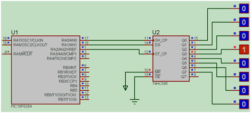
This makes the project a useful example of how a small microcontroller can control multiple LED channels efficiently.
How the PIC12F675 RGB LED Show Works
The PIC12F675 generates the sequence data that determines which RGB LED channels should turn on or off.
That information is sent serially to the 74HC595 shift register. The register receives the individual bits, stores them temporarily and then transfers the completed pattern to its output pins.
By repeatedly changing these output patterns, the circuit can create different color combinations and animated lighting effects.
Why the 74HC595 Is Used
The PIC12F675 has a limited number of available I/O pins, making direct control of many individual LED channels difficult.
The 74HC595 solves this problem by converting serial data from the microcontroller into multiple parallel outputs.
Three important signals are involved:
- Data carries the individual output bits.
- Clock moves each new bit into the shift register.
- Latch transfers the completed data pattern to the output pins.
This allows several outputs to be updated while requiring only a small number of PIC12F675 pins.
Correct 74HC595 Connections
The physical connections between the PIC12F675 and 74HC595 must match the pin assignments defined in the program.
If the data, clock or latch lines are connected differently from the software configuration, the LED sequence may not operate correctly.
The PIC12F675, 74HC595 and LED power supply must also share a common ground. Without the same ground reference, the logic signals sent between the devices may not be interpreted reliably.
Understanding the Latch Signal
The latch signal is especially important when controlling visible LED patterns.
The PIC first shifts all required bits into the 74HC595. Only after the complete pattern has been loaded should the latch signal transfer that data to the physical outputs.
If the latch changes while data is still being shifted, intermediate patterns may briefly appear on the LEDs and create unwanted flickering.
RGB LED Current-Limiting Resistors
Each RGB LED color channel should have an appropriate current-limiting resistor.
An RGB LED normally contains separate red, green and blue light-emitting elements. These individual colors can have different forward-voltage characteristics, meaning a resistor suitable for one channel may not necessarily produce the same current or apparent brightness in another.
Resistor selection should therefore consider:
- Supply voltage
- LED forward voltage
- Desired operating current
- Output capability of the driving circuit
The resistor also protects the LED from excessive current.
74HC595 Output Current Limits
The 74HC595 cannot safely supply unlimited current to connected LEDs.
When multiple RGB channels operate simultaneously, the combined load on the shift register can increase significantly. The current requirements of the LEDs should therefore be compared with the permitted output limits of the device.
If the LEDs require more current than the 74HC595 can safely provide, suitable transistor driver stages can be placed between the shift-register outputs and the LED loads.
This allows the shift register to control the switching while the transistors handle the higher current.
Common-Anode and Common-Cathode RGB LEDs
Another important consideration is the internal connection of the RGB LEDs.
RGB LEDs are commonly available in common-anode and common-cathode configurations. These two types require different output logic.
With one type, a logic-high output may activate a color channel, while the other configuration can require the opposite logic state.
Before troubleshooting the software, the RGB LED pinout and common connection should therefore be verified against the actual component being used.
Preventing Switching Noise
Rapid switching of the PIC12F675 and 74HC595 can produce short disturbances on the power supply.
Decoupling capacitors placed close to the power pins of both integrated circuits can help suppress these short voltage fluctuations and improve circuit stability.
Good power connections become increasingly important as more LED channels switch simultaneously.
Troubleshooting Incorrect RGB Patterns
If the PIC12F675 RGB LED Show produces incorrect colors, flickering or a permanently fixed pattern, several areas should be checked.
Start by confirming that the data, clock and latch connections match the C program. The latch should update the outputs only after the required bits have been shifted.
The RGB LED pin configuration should also be checked carefully because incorrect identification of the red, green, blue or common pins can produce unexpected colors.
Testing only one color channel at a time can make both wiring and programming problems easier to isolate.
Checking the LED Sequence
When troubleshooting the program, begin with a simple output pattern before testing complex animations.
For example, activating one LED color at a time can confirm whether:
- Serial data is reaching the 74HC595
- The clock signal is shifting data correctly
- The latch signal is updating the outputs
- Individual RGB channels are wired correctly
Once basic operation has been verified, more complex color sequences can be introduced.
Project Files and Simulation
The project includes supporting materials such as the circuit simulation, HEX code and demonstration video.
These files can help builders understand how the circuit was originally configured and provide a starting point for experimenting with different RGB sequences.
When adapting the original design, software pin assignments and the physical wiring should always remain consistent.
Final Overview
The PIC12F675 RGB LED Show demonstrates how a small microcontroller can control several RGB LED outputs by using a 74HC595 shift register.
The project combines serial data transmission, output expansion and RGB LED control in a relatively compact circuit. Correct data, clock and latch timing, suitable current-limiting resistors, proper grounding and awareness of the 74HC595 current limits are important for reliable operation.
For anyone learning PIC microcontrollers or shift-register-based LED control, the circuit provides a practical example of expanding limited microcontroller outputs to create programmable lighting effects.
Source: RGB LED SHOW PIC12F675 RGB led show PIC12F675 proteus isis simulation, pcband source code files: RGB led show PIC12F675 .ZIP
- What components are used to move sequential RGB lights?
The study uses the PIC12F675 and 74HC595 Integrator. - How can I view the application circuit simulation?
An ISIS video of the application circuit is available in the attached document. - Where can I find the hex code for this project?
The hex code is included in the attached document alongside the circuit video. - Does the article provide source code files?
Yes, the source code files are available in the RGB led show PIC12F675 .ZIP file. - What software is used for the Proteus simulation?
The project utilizes Proteus ISIS for the simulation. - Can I download the project files?
Interested friends can access the files through the provided link to the .ZIP archive. - What type of electronic projects does this fall under?
This is categorized as an RGB led show, microchip, microcontroller, and simple circuit project.
