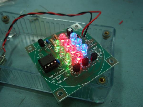
Want to build an RGB LED controller that you can program with your own custom sequences and effects? Then read on.
The RGB LED controller has proved to be very popular project and has been the most frequently downloaded code on the site since it was made available. I’ve been contacted by people who have incorporated this project into all kinds of things including mood lamps, lighting for a sculpture, accent lighting for rooms and an illuminated prize trophy.
For 2006 I completely rewrote the application making it much easier to add, edit and change the sequence data. I also added a sleep function so a battery operated version can be built that doesn’t need a power switch.
For 2008 I’ve released version 3 of the code which now allows you to stop the running sequence at any point so you can ‘freeze’ a colour.
All code runs on the 12F629, 12F675 and the newer 12F683 which, with 2K of program memory has plenty of room for user sequences.
Description
The original RGB PWM driver application that I wrote in 2004 had a few shortcomings. Probably the biggest was that it was not easy to add to or change the sequences. This new version addresses that problem, is more flexible and now includes the ability to put the PIC to ‘sleep’ and ‘wake’ it again using the sequence select switch, eliminating the need for an on/off switch in battery powered applications.
The circuit uses (RGB) Red, Green and Blue high brightness LEDs that are pulse width modulated (PWM) to vary the intensity of each colour LED. This allows effectively any colour to be generated with rapid changing strobe effects, fast and slow colour fades as well as static colours. The data used to set and change the colours is held in an easy to edit file so if you don’t like the sequences provided with it, you can modify the sequence data include file yourself and reprogram with your own sequences.
The code can be assembled for use with the following PICs: 12F629, 12F675, 12F683. Just select the correct processor in the MPLAB IDE before assembling.
How bright are the LEDs
That depends on the specific LEDs you use, the current you drive them with, the angle your view them from etc……..
If you want to know I suggest the best thing to do is buy the LEDs you’re planning to use and connect them up directly to a power supply using a suitable current limiting resistor. If the brightness meets your expectations than go ahead and build this project, but if they don’t they aren’t going to be any brighter in this circuit so you probably need to look at an alternative solution like a large array of LEDs driven with the Power MOSFET Driver project
Since I do not know exactly which LEDs you will use I’ve specified the LED current limiting resistors on the conservative side. You may want to change the value of these resistors to suit the actual LEDs used. Keep the current per channel to under 40mA maximum.
LED resistor calculator http://led.linear1.org/led.wiz
If you wish to etch your own board, you can download the PCB artwork as PDF![]()
For the component overlay, please refer to the photo’s below
For more detail: RGB LED PWM Driver Standalone PWM controller for RGB LEDs using PIC12F629

