Summary of RF MODULE INTERFACE TO 8051 MICROCONTROLLER
This article details interfacing a low-cost 315/433MHz RF module with an 8051 microcontroller for wireless projects like robotics and remote controls. The author explains the choice of 8051 for its cost-effectiveness despite the lack of built-in libraries, requiring manual UART implementation. The project utilizes a simplex communication protocol with a checksum for data authenticity. The tutorial covers hardware setup, including voltage regulation and crystal circuits, and software logic involving start bytes, addresses, and message verification to control devices remotely.
Parts used in the RF Module Interface to 8051 Microcontroller:
- 315/433MHz RF MODULE (TRANSMITTER AND RECEIVER PAIR)
- 8051 MICROCONTROLLER (AT89C4051 AND AT89S52)
- TWO BREADBOARDS
- BATTERY CLIPS
- 9V BATTERIES
- 7805 VOLTAGE REGULATOR
- PUSH BUTTONS
- LEDS FOR INDICATORS
- RESISTORS AND CAPACITORS
- 7 SEGMENT DISPLAY (OPTIONAL)
- PROGRAMMER FOR 8051 (TOP853)
This instructable covers the interface of 8051 microcontroller with the cheap 315/433MHz RF module. This comes in handy in different kinds of wireless connectivity projects like Robotics, Wireless Level sensors, etc. The sensor is really cheap, typically about $5. I have implemented this module with other controllers such as Arduino and Pic, but the 8051 tends to be more difficult, owing to the compiler. I used this sensor severally in designing remote control vehicles, drones and other devices that need a cheap wireless controller.
One question people may ask is “why 8051? I mean its so yesterday…” Well, I chose 8051 because the controller is really cheap, and for projects which do not require much peripherals like ADC, PWM, etc., I would go for the 8051. Also, its memory is almost in excess, and so you could call several functions without having issues (I usually have issues with several function calls in the PIC16 and PIC12f family. I get an error message usually about indirect addressing. PIC18 and dsPic overcome this issue, but they cost almost 5 times the price of an 8051 microcontroller!). Besides, so many tutorials already exist out there mostly for the Arduino and PIC microcontrollers. When I first wanted to build with my 8051, I surfed the net for tutorial for this, but I couldn’t find any, so I thought “…write up one to help guys out there who might be having challenge with this module…” and that’s exactly what I did. I stand to be corrected, but One challenge with the 8051 is that the official compiler (Keil) has no in built libraries, and as such it makes it more difficult to use, as opposed to the Arduino compiler, or Mikro C which has several in built libraries. User has to write much functions for virtually everything, so it becomes that the cost you save for buying the controller, you spend in the programming. That notwithstanding, This chip is still among my favorite.
Step 1: MATERIALS USED
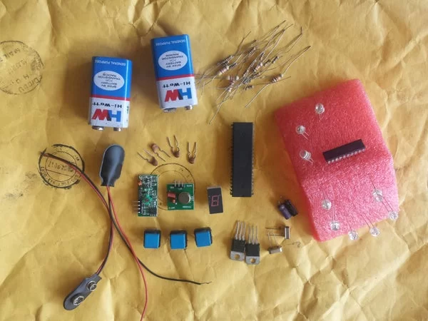
1. 315/433MHz RF MODULE (TRANSMITTER AND RECEIVER PAIR)
2. 8051 MICROCONTROLLER( ANY MEMBER OF THE FAMILY. I USED AT89C4051 AND AT89S52)
3. TWO BREADBOARDS
4. BATTERY CLIPS
5. 9V BATTERIES( OR ANY OTHER DC SOURCE)
6. 7805 VOLTAGE REGULATOR FOR THE MICROCONTROLLERS AND RF RECEIVER.
7. PUSH BUTTONS
8. LEDs FOR INDICATORS
9. RESISTORS, CAPACITORS.
10. 7 SEGMENT DISPLAY (OPTIONAL)
11. PROGRAMMER FOR 8051. I USED TOP853, BUT ANY PROGRAMMER WOULD SUFFICE.
12. MISCELLANEOUS.
Step 2: MICROCONTROLLER
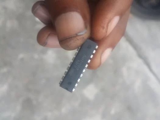
The 8051 is a family of 8 bit controllers that have been around for a while. Unlike some other standard controllers, they do not have an internal clock, and so a crystal is required. The datasheet gives a design of the crystal circuit, as well as the RESET circuit. I advise, on a general note, to always study the datasheet of the device in question, as many uncertainties will be made cleared. I would not write much on this controller, because I want to keep this instructable short and straightforward, but the datasheet should be downloaded for any issues with it. The controller has a RESET circuit, which comprises a 10uf capacitor and a 10k resistor. Without this circuit, the controller does not start up. Also, a standard 12MHz clock is most commonly used, although 24MHz could also work fine. However,on most applications i came across, and have used, the the 12MHz (or 11.059MHz) has been used frequently. Check out the image for the crystal and RESET circuits
Step 3: UART
UART stands for Universal Asynchronous Receiver Transmitter. It is also a serial protocol, which means the bits are transmitted or received one after the other, as opposed to parallel protocols where the entire bits are latched at once. It is also an asynchronous protocol, that is, communication without a common clock. The system therefore generates baud rates, which acts like a clocking system for the transmitter and receiver, so that both systems could communicate with the same ‘language’. Much credits go to ExploreEmbedded.com, as they generously provided a lot of libraries for the 8051 that helped out a lot. Also, they gave a lot of tutorials on 8051 UART, I recommend it. For more explanation on UART, you could also search it up, it is quite easy to comprehend. MikroC compiler has a USART library, and the Arduino has the Virtual Wire Library created by Mike McCauley. Keil compiler relies on the programmer actually writing the code for the entire system.
The baud rate is created using the internal timer of the microcontroller. 8051 has two timers, timers 0 and 1, which could run in 4 different modes. My system used timer 1 running in mode 2. For more information, read the datasheet of 8051 chips. These rf modules have a limited baud rate of 2400bps (bits/sec), so I chose to go to one immediately lower, which is 1200bps. This baud rate worked fine for me. The TXD is the Transmission terminal and goes to the RXT of the microcontroller, while the RXD is the Reception Terminal, and so goes to the TXD of the microcontroller (assuming we are using it on a microcontroller based system).
Step 4: RF MODULE

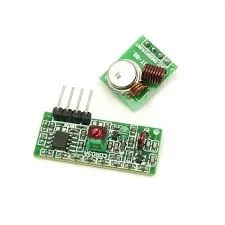
The RF module is a 315/433MHz module that has a transmitter and a receiver. RF stands for RADIO FREQUENCY. It allows only for a one way communication, that is it is a simplex kind of device. If you need a duplex connection, you need to buy two of it, or go for a higher end module that offers duplex communication.
The transmitter has three pins, Gnd for Ground, Vcc for Power and Data (sometimes erroneously spelt as ataD) which is the data output. The transmitter works all the way from 3V to 12V, with higher transmission strength gotten from higher voltage. For this design, I used a 5V source for the Vcc.
The data pin goes to the serial port of the microcontroller where the received byte is saved and processed. I advise viewers to also get the datasheet of this module so as to get more familiar with its working principles.
The receiver, on the other hand, is a 5v device which also has power, data and GROUND. Some modules have two data pins. Personally, I do not know why two pins were placed. You could tell me if you do, but both terminals are actually joined together. Once you put ON the transmitter, the receiver starts receiving garbage from every form of electrical noise around. I have attached also an image of my mini oscilloscope attached to the receiver pin when no data is sent. The level of garbage signals can be visibly seen. However, a software filter is Implemented to stop these garbage from corrupting the actual message. The microcontroller decodes the message using the UART protocol. Both transmission and reception is with the same protocol. Since the 8051 has no standard UART libraries, we are going to write our own.
Step 5: HOW IT WORKS
The principle our system works with is quite simple:
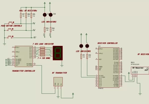
First We send a start byte, then the address byte. Finally, we send the massage byte and a check sum byte. Check sum is a kind of authenticity check where the controller adds the start byte to the address byte and confirms if the sum is actually equal to the check sum byte sent by the transmitter.This process is also used severally in infrared communication as well for authenticity of message or command. If check sum is the same both in transmitter and receiver, then it means that the message was authentic. The system now takes the data and does something with it based on its software code. I have attached my source files for both the transmitter and the receiver for whoever feels like doing the same project.
For my demonstration, I built my circuit on a breadboard. The aim was to keep it as simple as possible. We didn’t add LCD, maybe in subsequent tutorials, LCD will be used. Two microcontrollers, one for transmit and one for receive. The pictures shows the LEDs lighting up on the receiving end when the transmitter is pressed. Also, a video description is attached below. The system could be scaled to a bigger level, and be used even for automations, control systems, etc. The video does not include the 7 segment display, but the code includes the display interface to the transmitter on port 1. My transmitter and receiver modules have no antenna attached, but it still works fine. However, to get the maximum range, both modules require an antenna.
Attachments
Step 6: CONCLUSION
That’s all for now. Interface of the RF module to 8051 is quite easy, almost too easy. Our next tutorial will address interfacing it using the Interrupt Service Routine( as opposed to the polling technique that we used here). Much thanks to several great forums of electronic all over the web that has imparted to many of us. My library codes were gotten from ExploreEmbedded, I give credits to them for their ingenious work. Write your questions and comments below, and I will be more than happy to answer them. Also, if you enjoyed this tutorial please do well to like it.
Source: RF MODULE INTERFACE TO 8051 MICROCONTROLLER
- Why choose the 8051 microcontroller over Arduino or PIC?
The 8051 is chosen for its low cost and sufficient memory, making it ideal for projects not requiring many peripherals. - What baud rate was selected for the RF module communication?
A baud rate of 1200bps was selected because the modules have a limited rate of 2400bps. - How is the authenticity of the message verified in this system?
Authenticity is verified using a checksum byte where the controller sums the start and address bytes to confirm they match the sent checksum. - Does the 8051 microcontroller have an internal clock?
No, the 8051 does not have an internal clock and requires an external crystal circuit to function. - What type of communication does the RF module support?
The RF module supports one-way or simplex communication. - What components make up the RESET circuit for the 8051?
The RESET circuit comprises a 10uf capacitor and a 10k resistor. - Which timer mode was used to generate the baud rate?
Timer 1 running in mode 2 was used to create the internal baud rate. - Can the 8051 use built-in UART libraries from the official Keil compiler?
No, the official Keil compiler has no built-in libraries, so the user must write their own functions for UART. - What is the recommended power supply voltage for the transmitter?
The transmitter works from 3V to 12V, but a 5V source was used for this specific design.