Summary of Remote controlled USB mouse using PIC18F4550
This article details the construction of a USB mouse controlled by an infrared remote using a PIC18F4550 microcontroller. It outlines the necessary hardware components, including the MCU, IR receiver, and oscillator, and explains the circuit connections. The software section describes using CCS C compiler to decode NEC protocol signals via external interrupts and Timer1/Timer3 for pulse measurement and repeated code handling, enabling full-speed USB operation at 48 MHz.
Parts used in the Remote Controlled USB Mouse:
- PIC18F4550 microcontroller
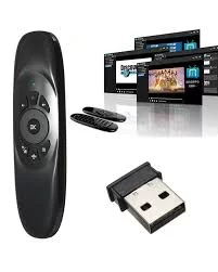
- IR remote control (NEC protocol)
- IR receiver
- 8MHz Crystal Oscillator
- 2 x 22pF capacitors
- 47uF polarized capacitor
- 470nF Capacitor
- 10K ohm resistor
- USB Connector
- +5V Power Supply
- Breadboard
- Jumper Wires
Building a USB mouse using PIC18F4550 microcontroller and CCS C compiler is easy as shown in the link below:
USB Mouse using PIC18F4550 microcontroller
Also, it is not hard to add an infrared remote control to the previous USB project. This post shows how did I build a simple IR remote controlled USB mouse using PIC18F4550 microcontroller and Car MP3 IR remote control (NEC protocol).
The link below shows how to decode NEC IR remote control (remote controls may not have the same code messages, so to know the code of each button we’ve to decode it first):
NEC Protocol decoder with PIC16F887 microcontroller
Hardware Required:
- PIC18F4550 microcontroller
- IR remote control (NEC protocol)
- IR receiver
- 8MHz Crystal Oscillator
- 2 x 22pF capacitors
- 47uF polarized capacitor
- 470nF Capacitor
- 10K ohm resistor
- USB Connector
- +5V Power Supply (USB VCC can be used)
- Breadboard
- Jumper Wires
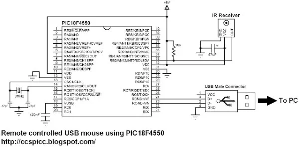
Remote controlled USB mouse using PIC18F4550 circuit:
The IR receiver has 3 pins: GND, VCC and OUT. The OUT pin is connected to RB0 (INT0 pin).
The circuit shown above is powered from an external 5V source which means there is no need to connect the VCC pin of the USB connector, but this pin can be used to supply the circuit and therefore the external 5V source has to be removed.
In this project the microcontroller runs with 8 MHz crystal oscillator and MCLR pin function is disabled.
Remote controlled USB mouse using PIC18F4550 C code:
The C code below was tested with CCS C compiler version 5.051.
In this project the PIC18F4550 MCU runs with 8 MHz crystal oscillator and it is configured so that the MCU runs at 8 MHz. I enabled PLL2 for the USB module in order to get 48 MHz which allows the USB module to run at full speed (12 Mbps).
The output of the IR receiver is connected to the external interrupt 0 pin (RB0/INT0) and with that I used it to decode the IR remote control. The NEC code massage is 32-bit long (2 words).
I used Timer1 to measure pulse and space widths and I used Timer1 interrupt to reset the decoding process in case of very long pulse or very long space (time out). Timer1 is configured to increment every 1 us. So for example for the 9 ms pulse I used the interval between 8500 and 9500.
I used Timer3 with the repeated remote control codes. If a button is pressed with hold the remote control will send the button massage code and then it sends 9 ms pulse –> 2.5 ms space –> 562 us pulse and so on every 110 ms. (more details at: http://www.sbprojects.com/knowledge/ir/nec.php)
From previous if a button is pressed with hold it will continuously sets Timer3 to the value 25000 ( set_timer3(25000); ). When the button is released Timer3 will overflow and its interrupt will reset the code message ( nec_code = 0; ).
Read more: Remote controlled USB mouse using PIC18F4550
- How is the IR receiver connected to the microcontroller?
The OUT pin of the IR receiver is connected to RB0, which functions as the external interrupt 0 pin. - Can the USB VCC be used to power the circuit?
Yes, the VCC pin of the USB connector can supply the circuit if the external 5V source is removed. - What clock speed is configured for the USB module?
The PLL2 is enabled to run the USB module at 48 MHz for full speed operation. - Which timer is used to measure pulse and space widths?
Timer1 is used to measure pulse and space widths and is configured to increment every 1 us. - How does the system handle a held button press?
When a button is held, Timer3 is set to 25000; when released, Timer3 overflows and resets the code message. - What compiler was used for the project code?
The C code was tested with CCS C compiler version 5.051. - Is the MCLR pin function disabled in this project?
Yes, the MCLR pin function is disabled while the microcontroller runs with an 8 MHz crystal oscillator. - What is the duration of the NEC code message?
The NEC code message is 32-bit long, consisting of 2 words.