Summary of Remote-Control Light Dimmer using pic microcontroller
The author converted a cheap Wal-Mart lamp into an IR remote-controlled dimmer using a homemade transmitter in a tin can. The system uses a 34 kHz 940 nm IR LED and a simple serial protocol: preamble 0xFF, header 0x06, 32-bit device ID ('A','B','L','1'), a 2-byte big-endian button code (0=power,1=brightness up,2=brightness down), checksum, and trailer 0xFF. Bit timing: 1 = 0.5 ms carrier + 1.5 ms off; 0 = 0.5 ms carrier + 0.5 ms off. The design supports many devices and buttons.
Parts used in the Remote-Control Light Dimmer:
- Wal-Mart lamp (existing lamp)
- Tin can enclosure (Altoids-style tin can)
- IR LED (940 nm)
- Driver/electronics for 34 kHz carrier modulation
- Microcontroller or encoder to generate protocol and timings
- Power supply for transmitter electronics
- Wiring and connectors
The lamp in my bedroom is a very cheap lamp from Wal-Mart. It stands in one corner of my room, opposite of the door. This is where the problem is: If it is dark, I have to walk across the room, not trip on anything, find the small knob to twist to turn on the lamp, walk back towards whatever I need to do in the room. That is a whole lot of unnecessary walking.
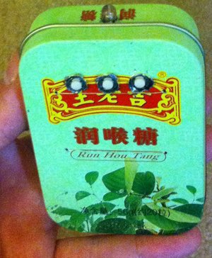 As can be imagined, this annoyed me. I decided to make a remote-control for the lamp. And since I was making a remote control, I decided that I might as well make it a dimmer – something I’ve wanted from this lamp for a while. I lacked any enclosures, so I used a tin can from what I can only assume were Chinese Altoids.
The IR protocol is very simple. At the physical layer I stole it from a previous project of mine. IR 940nm LED is used. The carrier frequency is 34KHz. A 1-bit is sent with 0.5 ms of modulated carrier and 1.5 ms of darkness. A 0-bit is sent with 0.5 ms of modulated carrier and 0.5 ms of darkness. The packet begins with a preamble byte of 0xFF. Then comes a header of 0x06. Then comes the device ID – a 32-bit identifier of the device. For this project, I used a device ID of {‘A’ ‘B’, ‘L’, ‘1’}. Then comes the button code.
 2 bytes are used, big-endian. This project uses just three button codes: 0 for “power on/off”, 1 for “brightness up,” and 2 for “brightness down.” Then comes a checksum. It is used to make sure that the packet is received successfully and error-free. Then comes the trailer byte of 0xFF. This protocol allows for over 4 billion device types and more than 65 thousand buttons for each.
For more detail: Remote-Control Light Dimmer
- What carrier frequency does the remote use?
The remote uses a 34KHz carrier frequency. - What wavelength is the IR LED?
The IR LED is 940nm. - How is a 1-bit encoded in the protocol?
A 1-bit is 0.5 ms of modulated carrier followed by 1.5 ms of darkness. - How is a 0-bit encoded in the protocol?
A 0-bit is 0.5 ms of modulated carrier followed by 0.5 ms of darkness. - What is the packet structure of the protocol?
The packet is: preamble 0xFF, header 0x06, 32-bit device ID, 2-byte big-endian button code, checksum, trailer 0xFF. - What device ID was used in this project?
The device ID used was the four characters A B L 1. - Which button codes are used and what do they do?
Button codes used are 0 for power on/off, 1 for brightness up, and 2 for brightness down. - How many device types and buttons does the protocol support?
The protocol allows over 4 billion device types and more than 65 thousand buttons for each.