Summary of RDS/RBDS decoder with optional FM stereo receiver using PIC18F452
This project decodes RDS (Europe) and RBDS (USA) from FM tuners (88–108 MHz), displaying station info, time, program text, and status on either a 4x20 character LCD or a small graphical LCD; optional RS232 output and an integrated FM stereo tuner with headphone amp are included. The PIC18F452 controls decoding and display; TDA7330 handles MPX/RDS input. Joystick selects display and controls tuning/volume; settings are stored. Schematics, PCB (Eagle 4.11e) and hex file are provided.
Parts used in the RDS/RBDS decoder with optional FM stereo receiver:
- TDA7330 (RDS/RBDS decoder chip)
- PIC18F452-I/L PLCC microcontroller
- 4x20 character LCD module
- Graphical LCD LPH7779 (Nokia 3310 LCD)
- Joystick for digital tuning and volume control
- 47 nF coupling capacitor (for MPX input)
- FM stereo tuner section components (as per schematic)
- Headphone amplifier components (as per schematic)
- RS232 interface components (as per schematic)
- Pcb and schematic files (Eagle 4.11e) and hex file
This project supports both RDS (Europe) and RBDS (USA) Tuner FM band 88..108 MhZ (Europe and USA.)
You can choose between a 4×20 character LCD or a smaller graphical LCD to display data. A simple RS232 interface can also be used.
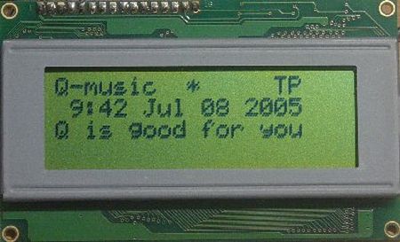
A 4×20 character LCD module will display these:
- 1st row: Station name (PS), Quality, Program Identification (PI), Traffic Program (TP) and Announcement (TA)
- 2nd row: Time and Date (CT)
- 3rd row: Radio Text Line A (RT) 64 scrolling characters.
- 4th row: Radio Text Line A (RT) 64 scrolling characters.
All major parts are available from our online shop.
Schematic & pcb (Eagle 4.11e), hex file available. Last updated on December 12, 2007.
Circuit explanation
The schematic consists of two major subcircuits:
-
The actual RDS/RBDS Decoder with the PIC and the display.
-
The FM Stereo tuner with headphone amplifier.
If you want to build this decoder into an existing tuner, then you won’t need to rebuild the tuner part of the circuit. All you need to do then is to look for an MPX-signal in your existing tuner. This is usually found before the stereo decoder chip. This MPX signal must then be fed to the TDA7330 through a 47nF capacitor.
The circuit needs a couple of seconds of valid RDS/RBDS data before driving the LCD.
Quality indicator: a stable arrow (first row on the LCD) means the reception is good. Blinking arrows however indicate no valid RDS/RBDS data is being processed (signal too weak or station transmits no RDS/RBDS data.)
Digital tuning and volume control: the joystick gives us to have full control over the circuit. Last values are stored and reloaded on boot.
You’ll have to choose a 4×20 character LCD or a smaller graphical LCD to display data. The smaller graphical LCD is best suited for portable applications, whereas the larger 4×20 character LCD is best for fixed receivers (f.e. in your car). Which display is driven can be chosen when booting: joystick-left for the 4×20 and joystick-right for the smaller LCD.
The RS232 interface also shows all decoded data properly (see the screenshot below.)
| RDS decoder: | ||
| TDA7330 | RDS/RBDS decoder chip. Needs an MPX input in order to decode RDS/RBDS data. | |
| PIC18F452-I/L PLCC | This Microchip PIC microcontroller does most of the work: it looks for valid RDS data, then drives the LCD. | |
| Graphical LCD | Nice little graphical LCD LPH7779 (Nokia 3310 LCD) Low power and best for portable use. Contrast adjustment by pressing volume up or volume down whilst booting. | |
| LCD Module 4×20 | Standard 4-lines x 20-characters LCD module. Best choice for fixed receivers. | |
For more detail: RDS/RBDS decoder with optional FM stereo receiver using PIC18F452
- Does the project support both RDS and RBDS?
Yes, it supports RDS (Europe) and RBDS (USA) on the FM band 88..108 MHz. - What display options can be used with this project?
You can choose a 4x20 character LCD or a smaller graphical LCD LPH7779 (Nokia 3310 LCD). - Can I integrate the decoder into an existing tuner?
Yes, you can feed an existing tuner's MPX signal to the TDA7330 through a 47nF capacitor and skip rebuilding the tuner section. - How is display selection made at boot?
Display is chosen at boot with the joystick: joystick-left for the 4x20 LCD and joystick-right for the smaller graphical LCD. - What indicates good RDS reception on the LCD?
A stable arrow on the first LCD row indicates good reception; blinking arrows indicate no valid RDS/RBDS data. - Does the project provide serial output of decoded data?
Yes, a simple RS232 interface can be used to show all decoded data. - Which chip decodes the RDS/RBDS data?
The TDA7330 handles MPX input and RDS/RBDS decoding. - Which microcontroller controls decoding and the display?
The PIC18F452-I/L PLCC microcontroller performs the decoding tasks and drives the LCD. - How long does the circuit need before driving the LCD?
The circuit needs a couple of seconds of valid RDS/RBDS data before driving the LCD. - Are schematics and firmware available?
Yes, schematic and PCB (Eagle 4.11e) and a hex file are available; last updated December 12, 2007.