Summary of Proteus Tutorial – Light Emitting Diode (LED) and Bar Graph Display
This article explains how to use Light Emitting Diodes (LEDs) in Proteus simulation software. It details locating active LEDs under the Optoelectronics library, selecting components like batteries and resistors, and calculating series resistance using a specific formula to prevent damage. The guide emphasizes setting components to 'ACTIVE' for real-time simulation and editing resistor values directly within the software.
Parts used in the LED Proteus Simulation:
- Battery
- LED
- Resistor
How to work with Light Emitting Diode (LED) in Proteus
In this post we will be learning on how to use the “Light Emitting Diode (LED)” component in Proteus simulation software. In case you have not got on through the basics of Proteus, here is the link – Proteus PCB Design and Simulation Software – Introduction.
Note:- You may also read our 1st chapter on Proteus Tutorial Series – Switches and Relays in Proteus before you continue reading this chapter.
Types of LEDs available in Proteus
Proteus contains LEDs of different colors and types that are being used in real time applications.
LEDs are found in Proteus software under Library category Optoelectronics. Remember to select ‘ACTIVE’ components so that the simulator provides real time interface during simulation.
- Step 1: Select component mode.
- Step 2: Click on Pick devices ‘P’.
- Step 3: Scroll down categories to find ‘Optoelectronics’ or alternatively type LED in Keyword. Select
this category and it shows the available LEDs in the result. - Step 4: Scroll to find the required LEDs according to circuit.
- Step 5: Remember to select components with ACTIVE property under Library column of the search
results for interactive simulation.
Using LEDs in Circuits
LEDs must be powered with voltages under specified limits, so that safe current flows through it without damaging. It is better to use a series resistance to ensure it is under Safe Operating Area(SOA).Formula to calculate series resistance is
Rs = (Vsource–Voltage drop of LED)/(Maximum Forward Current)
Applying this formula to LED of 2 Volts drop and 20mA forward current for a source voltage of 5Volts, gives series resistance of 150 Ω.
Rs = (5-2)/0.02 = 150 Ω
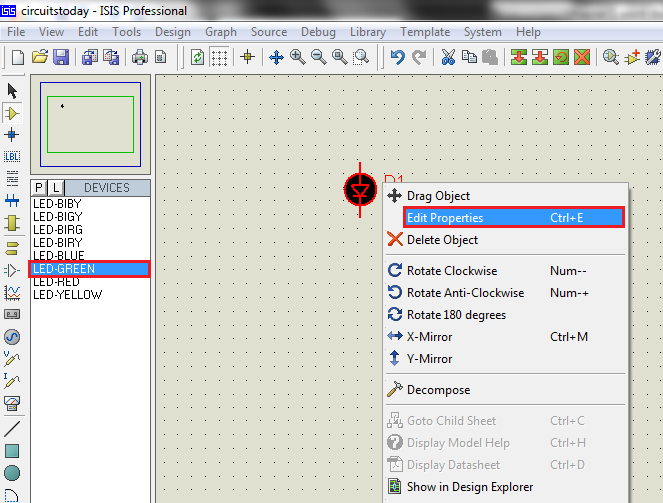
Step 1: Select components required i.e.., Battery, LED and resistor. Resistor of required value may not be available, but choose any valued resistor and edit its resistance in Edit Properties Tab. Wattage of resistor need not to be considered while simulation until PCB layout is expected. In hardware implementations, it is to be chosen according to LED and source voltage.
For More Details : Proteus Tutorial – Light Emitting Diode (LED) and Bar Graph Display
- Where are LEDs located in the Proteus library?
LEDs are found under the Library category Optoelectronics. - What property must be selected for interactive simulation?
You must select components with the ACTIVE property under the Library column. - Why is a series resistance necessary when using LEDs?
A series resistance ensures safe current flows through the LED without damaging it. - What is the formula to calculate series resistance?
The formula is Rs = (Vsource–Voltage drop of LED)/(Maximum Forward Current). - How do you handle a resistor value that is not available in the list?
You can choose any valued resistor and edit its resistance in the Edit Properties Tab. - Is wattage considered for resistors during simulation?
Wattage of the resistor need not be considered while simulating until PCB layout is expected.