Summary of Programmable relay switch using PIC MCU (revised version)
This article details a DIY programmable relay switch using the PIC16F1847 or PIC16F628A microcontroller. It features adjustable ON/OFF times up to 99 hours and 59 minutes, a cyclic operation mode, and data retention via internal EEPROM. The device includes an interactive interface with four push switches and a 16×2 LCD, along with an on-board buzzer alarm and voltage regulator for 9-15V DC input.
Parts used in the Programmable Relay Timer Switch:
- PIC16F1847 microcontroller
- PIC16F628A microcontroller (alternative)
- LM7805 linear regulator chip
- Relay
- 16x2 character LCD
- Four tact switches
- On-board buzzer alarm
- EEPROM (internal to microcontroller)
- Optical isolator
- PCB board
- 2-pin terminal block
- 2.1mm DC barrel jack
Programmable relays are key elements in numerous automation applications such as automatic street light control, watering and pump control, HVAC, home automation, power plants automation in industries, etc. This article describes a DIY programmable relay switch using PIC16F1847 (PIC16F628A can also be used) microcontroller. It is a revised version of my previous PIC-based relay timer project with added features and some improvements in the circuit design part. Like my previous version, it also allows you to set both ON and OFF times. The maximum time interval that you can set for ON and OFF operations is 99 hours and 59 minutes. The new version features cyclic option, which means you can choose to run it in a continuous loop of ON and OFF cycles. The timer can be programmed through 4 push switches. The programming menu, relay status (ON or OFF), and number of cycles completed are displayed on a 16×2 character LCD. The timing resolution of this relay timer is 1 minute. The timer also saves the previously-set ON/OFF times and the cyclic option in its internal EEPROM so that it can retain these values after any power supply interrupt. The firmware for this project is provided for both PIC16F1847 and PIC16F628A microcontrollers.
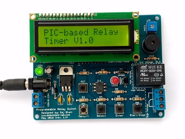
Here are the summary of the features that this programmable relay switch has:
- On-board +5V voltage regulator (operates at 9-15V DC input)
- OFF and ON time setup for the relay operation
- Option for cyclic run (maximum 100 cycles, after which the timer stops automatically)
- Stores ON/OFF times and Cyclic option from previous setup into internal EEPROM
- ON/OFF timing range: 0 to 99 hours and 59 minutes with 1 min resolution
- Interactive user interface using 4 tact switches and a character LCD
- On-board buzzer alarm
You can buy the PCB for this project from Elecrow.
Circuit diagram
Let’s first talk about the hardware part of this relay timer project. It is not much different than the previous version except for a few improvements, such as an optical isolation between the microcontroller I/O pin and the relay control circuit, which will be discussed later.
Power supply: The entire circuit runs off a regulated 5V power supply derived from the LM7805 linear regulator chip (Figure 1). To minimize the heat dissipation in the voltage regulator, the recommended input DC voltage is 9V, which can be easily obtained from a DC wall adapter. The circuit board contains a 2-pin terminal block and a standard 2.1mm DC barrel jack to receive the unregulated input DC voltage. There is no power supply ON/OFF switch available on board this time.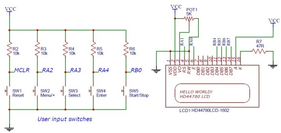
For more detail: Programmable relay switch using PIC MCU (revised version)
- Which microcontrollers are compatible with this project?
The firmware supports both the PIC16F1847 and the PIC16F628A microcontrollers. - What is the maximum time interval for ON and OFF operations?
The timer allows setting intervals up to 99 hours and 59 minutes with a resolution of 1 minute. - Can the timer run in a continuous loop automatically?
Yes, it features a cyclic option that runs a continuous loop of ON and OFF cycles up to a maximum of 100 cycles. - How does the device handle power supply interruptions?
The timer stores previously set ON/OFF times and the cyclic option in its internal EEPROM to retain values after power loss. - What input voltage range does the circuit operate on?
The circuit accepts an unregulated DC input voltage between 9V and 15V. - How is the timer programmed by the user?
Programming is done through four push switches that interact with a 16x2 character LCD display. - Is there an audible alert feature included?
Yes, the design includes an on-board buzzer alarm. - What improvement was made regarding the relay control circuit?
The revised version adds optical isolation between the microcontroller I/O pin and the relay control circuit.