Summary of UP/DOWN counter with memory
This project is a simple digital counter using a PIC16F88 microcontroller, featuring an RS-232 serial interface and a 7-segment display. Designed primarily for counting shelf items, it stores counts in internal EEPROM and uses SMD components. The system employs PORTA for direct segment driving with current-limiting resistors and PORTB for multiplexing displays via transistors and reading push-button switches with pull-up resisters. It includes an ICSP connector for programming, an untested RS-232 level converter for PC communication, and a 5V power supply that also handles serial data lines. A spare header allows for future expansion.
Parts used in the UP/DOWN Counter:
- PIC16F88 microcontroller
- 7-segment display (common anode)
- 100R resistors
- Transistors
- Push-button switches
- Pull-up resistors
- ICSP connector (SV1)
- RS-232 level converter chip
- 5V power connector
- Two-pin small header
This is a simple digital counter with a serial rs-232 and a 7 segment display, i started this project to count items on some shelfs, but it can be used for anything, it is also, for the exception of the connectors, completely on SMD components.
The circuit is made around a PIC16F88, and takes use of its internall EEPROM to store the number.
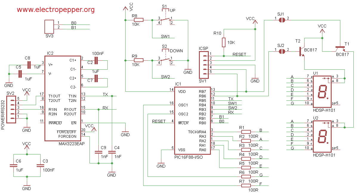
Im using PORTA to connect directly to the segment display thru a 100R resistor in each segment to protect each segment of the displays, then i use two lines from PORTB to multiplex the displays into showing units and decimals, by using the timer2 overflow interrupt with the presler at 1 meaning, if im not rong, that the display refresh at 250 nanoseconds thus impossible for the human eye to see. Each of this two lines connect first to the base of a transistor that drives the common anode on the 7 segment display, this way i spare my chip from suplying the main current thru it,prevents overheating and its always good practice to get power from the source.
Also on PORTB there are two lines from the switches, both switches have a pull-up resistor so when the button is pressed they go to ground, so the PIC is reading a 0 if the button is pressed.
I puted also a standard ICSP connector SV1, you can actually use this configuration of the ICSP connector to almost any microchip microcontroller, at least until today i havent found one that it didnt work.
The second chip on the schematic is a standard rs-232 level converter, ive wired it as in the datasheet and connected on the PIC AUSART(Addressable Universal Synchronous Asynchronous Receiver Transmitter) module, its the only part of the circuit not tested yet, i havent made any code to work with it.
The entire circuit is powered directly with 5V from the connector wich includes also the serial TX and RX lines to connect to a PC, i can later also see the numbers on the computer and even insert numbers into it, also ill write software to read several counters and colect the data into a computer to monitor shelfs items and manage stock.
And finally i have a two pins small header with the last remaining unconected pins, i usually do this so i can access them in the future if necessary, for example to add more functions to the circuit.
For more detail: UP/DOWN counter with memory
- What is the main purpose of this project?
The project was started to count items on shelves but can be used for anything. - How does the circuit protect the 7-segment display segments?
It connects PORTA directly to the display through a 100R resistor in each segment. - Can I use the same ICSP connector configuration for other microcontrollers?
Yes, this configuration works with almost any Microchip microcontroller. - How are the buttons connected to the PIC?
Two lines from PORTB connect to switches with pull-up resisters so the PIC reads a 0 when pressed. - Does the PIC supply the main current for the display?
No, transistors drive the common anode to prevent overheating and spare the chip from supplying main current. - Is the RS-232 functionality currently working?
No, the RS-232 part has not been tested yet as no code has been written for it. - What voltage powers the entire circuit?
The circuit is powered directly with 5V from the connector. - Why is there a two-pin small header included?
It provides access to remaining unconected pins for future function additions.