
Summary of Precision Delay Timer for PIC16F628A
This project is a crystal-controlled precision timer offering delays from 1 second to 15 hours 45 minutes, set by a 10-way DIP switch. It starts on a falling edge at Start (onboard button, external switch, or logic input), can be cancelled via Clr, and optionally supports retriggering. Two LEDs indicate active delay and a 1 Hz heartbeat. Outputs include a logic-level timer output and an onboard relay for switching loads. DIP switch 10 selects retrigger mode; ranges and multipliers are selected by the other DIP positions.
Parts used in the Precision Timer:
- Crystal (frequency not specified)
- PIC16F628A microcontroller
- 10-way DIP switch
- Start pushbutton (S1) on main PCB
- Clr pushbutton (S2) on main PCB
- Terminal block for Start, Clr, Gnd, and outputs
- On-board relay for switching external loads
- Logic level timer output circuitry
- Active indicator LED
- Heartbeat LED (1 Hz blink)
- Supporting passive components (resistors, capacitors)
- PCB with connectors and wiring
Description
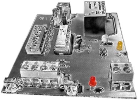
| This project is a crystal controlled precision timer providing accurate delays from 1 second to 15 hours 45 minutes. The timer delay is set using a 10-way DIP switch. The timer is started by pressing a switch on the main PCB or from an external switch connected via the terminal block connection. A second switch and terminal block connection allow the timer delay to be cancelled.
There are two LEDs on board, one provides indication of the timer delay active, and the other is a blinking ‘heartbeat’ LED to show the timer is running. The circuit provides a logic level timer output via a terminal block connection as well as the on-board relay for switching external loads. |
Operation
The timer delay period is set using the 10-way DIP switch. The DIP switch is used to select a time interval and multiplier to give the actual delay time. As the length of the delay time increases the adjustment interval gets courser.
The timed delay is started by a falling edge at the Start input and can be cancelled at any time by taking the Clr input low. In re-trigger mode, the time delay can be restarted while the timer is active.
Timed delay is started by a falling edge on the ‘Start’ input. This can be done in several ways:
- Press the S1 ‘start’ switch on the board.
- By external switch connected between the ‘Start’ and ‘Gnd’ connection of the terminal block
- Logic level input at the terminal block
The Timed delay can be cancelled at any time by taking the ‘Clr’ input low. This can be done in several ways:
- Press the S2 ‘clr’ switch on the board.
- By external switch connected between the ‘Clrt’ and ‘Gnd’ connection of the terminal block
- Low logic level input at the terminal block
Examples below illustrate Precision Timer operation (examples use 5 second timer period)
Timer delay triggered by falling edge at Start input
While timer delay active, heartbeat LED blinks at 1Hz
Time Delay Restart mode
When the timer is running it can be set to re-trigger (restart) using DIP Switch 10.
When re-trigger is enabled, a falling edge (Start button pressed) while the timer is running will reset the timer back to the start of the delay period. For example, if the delay period is 45 minutes and the timer is re-triggered after 20 minutes, the time period will be 20 minutes + 45 minutes giving a total timed delay of 65 minutes. The timer can be re-triggered at any time while it is active and it can be re-triggered multiple times.
If the timer is set to Non-retriggerable, once the timed delay is active it cannot be retriggered and will time out when the preset delay period has elapsed.
For more detail: Precision Delay Timer for PIC16F628A
- How is the timer delay set?
The timer delay is set using a 10-way DIP switch which selects a time interval and multiplier to give the actual delay. - How do you start the timer?
The timer starts on a falling edge at the Start input by pressing S1, using an external switch between Start and Gnd, or by a logic level input at the terminal block. - How can the timed delay be cancelled?
The timed delay can be cancelled by taking the Clr input low via S2, an external switch between Clr and Gnd, or a low logic level input at the terminal block. - What range of delays does the timer provide?
The timer provides delays from 1 second up to 15 hours 45 minutes. - Does the timer have an indicator to show it is running?
Yes, there are two LEDs: one indicates the timer delay is active and the other is a heartbeat LED that blinks at 1 Hz while the timer runs. - Can the timer be retriggered while running?
Yes, if DIP Switch 10 enables re-trigger mode, a falling edge at Start while running will restart the delay period; if disabled it cannot be retriggered. - What outputs does the circuit provide?
The circuit provides a logic level timer output via the terminal block and an onboard relay for switching external loads. - How does retriggering affect the total timed delay?
When retriggered, the current elapsed time remains and the full preset delay is added, so the total becomes elapsed time plus the preset delay.
