Since I first released this circuit for a serial PICMicro programmer, I have been getting lots of feedback from people that have been building it as their first PICMicro programmer. It has been really nice to hear comments from people about their experiences building the “El Cheapo” as well as questions and comments calling for enhanced capabilities. This is the fourth update to this article with a yet again modified version of the circuit to allow Serially Programmed EPROM PICMicros to be processed. The ability to program EPROM devices has been high on a number of people’s lists. In the article below, I will be making some comments about what I have found out about EPROM programming versus EEPROM/Flash programming.
If you have already built an El Cheapo, you will find that the modifications are very simple to make. Later in the article, I will outline what the changes are.
I am anticipating that this is the last modification to the El Cheapo circuit design. This does not mean that the programmer will remain static. Over the next few weeks, I will be releasing the Gerber files for a “Bare Board” version of the programmer and I will be creating a Visual Basic Interface for Windows for the programmer. Please let me know if there is anything else, you would like to see added to this programmer design.
If you have built an El Cheapo, I would appreciate it if you could send me some scanned in, or digital pictures of your programmer. I would like to add the pictures to this article to show other people the different ways in which the El Cheapo can be built.
The “El Cheapo” PICMicro programmer uses a PC’s “Parallel” (“Printer”) port port to program and verify the contents of a PICMicro PIC16F84 microcontroller. The features of this programmer includes very low cost, a large amount of independance from differing PC hardware as well as a diagnostic utility to help new builders successfully create their own programmer with a minimum of support. I have heard back from users which have used the programmer with the original PC’s (uni-directional) Parallel Ports as well as PC/AT “Bi-Directional” Ports and modern ECP/EPP Ports. I’m happy to say that I have achieved a certain amount of device independance with this design that I was looking for when I was designing the programmer for “Programming and Customizing the PIC Microcontroller”.
The code has been designed to work with as many of the different parallel ports in as many different implementations as there seems to have been released for the PC. In modern PCs, the Parallel Ports are normally at “base” addresses 0x0378 and 0x0278 of the PC Processor’s I/O space. For some parallel ports (especially ones that are integrated with other hardware), port 0x03BC is used as the base address. I have updated the “ElCheapo” and “ElDebug” applications to check the internal tables in the PC for the correct I/O port address for the specified “LPT” number.
The El Cheapo has generated quite a bit of interest from people. Checking over my email logs, I have received messages from over fifty people now that have built the programmer. Many of these people have suggested improvements to the programmer and over the last four iterations of the design of the card and the two software applications, quite a few of these changes has been made.
The History of these changes are:
| Version 1.00 – | Initial Release of the Programmer |
| Version 2.00 – | Modification of the Programmer to not use D0 Pin Release of “El Debug” Test Application |
| Version 2.10 – | Modification to “El Cheapo” and “El Debug” software to work with PC Parallel Port “Table” addresses, rather than hard coded addresses |
| Version 3.00 – | Initial Version of the EPROM capable “El Cheapo”. This was sent out to a limited number of people to test out the reset circuitry. The design used two 2N7000s and did not require changes to the elcheapo.exe and eldebug.exe applications |
| Version 3.10 – | The second 2N7000 was removed from the circuit and both elcheapo.exe and eldebug.exe were modified to work with reset which is inverted from the original design. |
Click HERE for the “Version 3.10” Updated Files in .ZIP Format.
The El Cheapo (like all Serial PICMicro programmers) will not work with the PICMicros which require parallel programming (the “Low-End” 16C5x and the “High-End” 17Cxx). For these devices, another programmer will have to be used.
I should point out that the El Cheapo is considered by Microchip as a “Developmental Programmer” and not a “Production Programmer”. For a programmer to be considered suitable for “Production”, it must be able to program and verify the part at different voltage levels.
I’m pleased with the versatility of the El Cheapo and how well it has worked for different people. As I indicated above, I think I have finalized the circuit design, but there are two upgrades I will be making in the coming weeks. They are:
1. Designing an embedded circuit board for the El Cheapo. The “Gerber” files for this board will be placed on this web page (as well as my own). The board will be designed for single-sided assembly, but I will be including a “Top Side” pattern for proto-shops like AP Circuits.
No decision has been made on selling the boards – but if you are interested, please let me know and based on the interest generated in the boards we’ll make a decision on whether or not to sell them. If you send me an email requesting the boards, please identify if you would like a kit of parts as well.
2. Creating a Visual Basic Interface application. This application will encompass both the “El Cheapo” Programmer software as well as the “El Debug” test application.
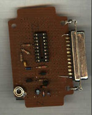
As part of the interest generated by this project, I would be interested in getting photographs of your El Cheapos. If you have built one and have access to a digital camera or scanner, I would love to see one or two pictures of your creations that we will put on this page. The purpose of doing this will be to show the prototyping methods that you have used for others as well as list any modifications that you have come up with for the circuit that might be of use to others.
This is the third version of the “El Cheapo” circuit. If you had built the previous version, then the following changes are made to the circuit to bring it up to the Version 3.1 standard:
1. Disconnect U1’s (the Voltage Regulator) ground from the circuit ground and add two IN914 diodes between the voltage regulator ground and the circuit ground.
These two silicon diodes will each “raise” the ground reference to the voltage regulator by 0.7 Volts. The two of them in series will raise the voltage regultor’s ground referency by 1.4 volts. After doing this the voltage regulator will output 13.4 volts relative to circuit ground for the EPROM programming.
2. Disconnect the “_MCLR” (Pin 4) of U2 (The Programmed Part) from the drain of the 2N7000 transistor.
Add a 2106a PMOS FET transistor with its drain connected to the 13.4 Volt Regulated Output, its gate to the drain of the 2N7000 (the connection that used to by to U2’s _MCLR pin) and its source to U1’s _MCLR.
In my point to point wired prototype, I was able to make these modifications in about ten minutes.
One of the aspects of the PICMicro that makes it very attractive for starting out with microcontrollers is the simple serial interface that is used to program the mid-range EEPROM (“Flash”) and EPROM based devices. Along with Vdd (+5V) and Gnd, the Reset Pin (“_MCLR”) and two I/O pins are used for programming the device. In the 16F84 (and other serially programmed PICMicros), these two pins are RB6 for “clocking” and RB7 for bi-directional “Data”. The operation of the programming is quite simple.
To set the device in “Program Mode”, the “Clock” and “Data” lines are pulled low and “_MCLR” is driven to +12 Volts. Data is sent with a six bit “Command” and optionally followed by a sixteen bit “Word”. This data is sent synchronously, with the “Data” value output before the “Clock” is strobed high. The data consists of the fourteen bit data word with a leading and trailing “0” sent or received to round up to sixteen bits.
You can download Microchip’s 16F84 programming datasheet from: http://www.microchip.com
This document contains all the information needed to program the 16F84, including timing and the “Command” word definitions. For the programmer described below, this was the only reference that I used. Microchip has also provided Application Note 589 (“AN589”) with their design for a simple Parallel Port Programmer which can be downloaded from: http://www.microchip.com along with all of Microchip’s other Application Notes.
For more detail: PICMicro Programmer with the “ElCheapo” using PIC16F84