
Summary of Right-left scrolling LEDs
This project implements a right-left scrolling LED display using a PIC16F627 microcontroller. Eight LEDs connected to PORT B scroll based on the state of a push-button switch attached to PORT A bit 0. Pressing the switch triggers rightward scrolling, while releasing it causes leftward movement. The system operates on a 4 MHz internal clock with a 250 ms delay between shifts and uses PicBasic for programming logic to manage I/O directions and button states.
Parts used in Right-Left Scrolling LEDs:
- PIC16F627 Microcontroller
- 8 LEDs
- Push-button Switch
- 330 Ohm Current-limiting Resistors
- Pull-up Resistor
- External Reset Button
- 4 MHz Internal Clock
Project description:
In this project, 8 LEDs are connected to PORT B of a PIC microcontroller. Also a push-button switch is connected to bit 0 of PORT A using a pull-up resistor.. When the switch is pressed the LEDs scroll to the right.
Hardware:
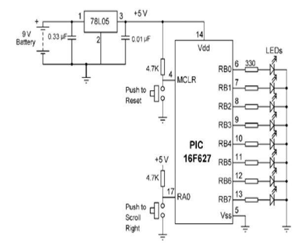
The circuit diagram of the project is shown in Figure 1. The circuit in this project additionally a switch is connected to bit 0 of PORTA to control the direction of scrolling. A PIC16F627 model PIC micro controller is used and the micro controller is operated from its 4 MHz internal clock. The LEDs are connected to 8 pins of PORT B using 330_ current-limiting resistors. An external reset button is connected to MCLR input of the microcontroller.
Flow diagram:
The flow diagram of the project is shown in Figure 2. At the beginning of the program the I/O direction is specified. A byte variable called Cnt is used as the loop variable. The program consists of an indefinite loop and at the beginning of the loop the switch is tested. If the switch is logic 1 (i.e. switch is not pressed) then the scrolling is to the left and if the switch is pressed the switch is at logic 0 and scrolling is to the right. A 250 ms delay is used between each output.
Software: Pic Basic
The software for PicBasic language is given in Figure 3. At the beginning of the program PORTA, PORTB, TRISA, TRISB, and CMCON register addresses are defined. TRISA is set to 1 so that bit 0 of PORTA is configured as an input port. Similarly, TRISB is cleared to 0 so that all bits of PORTB are configured as outputs. Push-button switch is connected to bit 0 of PORTA (RA0). Normally this pin is pulled high to logic 1 by using a resistor. When the switch is pressed the pin goes down to logic 0. PORTA pins on the PIC16F627 microcontroller have dual functions and they can either be used as analog comparator inputs, or as digital I/O ports. CMCON register is used to control the function of these pins. Setting CMCON to 7
configures PORTA pins as digital I/O ports. Inside the LOOP, the value of Cnt is sent to PORTB and the PEEK instruction is used to read the switch setting. “Bit0” refers to bit 0 of variable “B0” which is where the switch is connected. When the switch is pressed the program jumps to label PRESSED where the LEDs are scrolled right. When the switch is not pressed the LEDs are scrolled left. This loop is repeated forever with 250 ms delay between each output. Set port directions
‘*************************************************************************
‘ RIGHT-LEFT SCROLLING LEDS
‘ =========================
‘ 8 LEDs are connected to PORTB of a PIC microcontroller. This program
‘ scrolls the LEDs to the right or left depending on a switch setting. The switch
‘ is connected to bit 0 of PORT A. If the switch is not pressed the switch
‘ output is at logic 1 and the LEDs scroll to the left. When the switch is
‘ pressed the LEDs scroll to the right. A 250ms delay is used between each
‘ output.
‘*************************************************************************
 ‘ SYMBOLS
‘
Symbol TRISA = $85 ‘ TRISA address
Symbol TRISB = $86 ‘ TRISB address
Symbol PORTA = $05 ‘ PORTA address
Symbol PORTB = $06 ‘ PORTB address
Symbol CMCON = $1F ‘ CMCON address
Symbol Cnt = B1 ‘ Cnt is a byte variable
Symbol Switch = B0 ‘ Switch is a byte variable
‘
‘ START OF MAIN PROGRAM
‘
POKE CMCON, 7 ‘ RA0-RA3 are digital I/O
POKE TRISA, 1 ‘ Set PORTA bit 0 as input
POKE TRISB, 0 ‘ Set all PORTB pins as outputs
For more detail: Right-left scrolling LEDs
- What controls the direction of the LED scrolling?
The direction is controlled by a push-button switch connected to bit 0 of PORT A; pressing it scrolls right, while releasing it scrolls left. - How does the system behave when the switch is not pressed?
When the switch is not pressed, the pin remains at logic 1, causing the LEDs to scroll to the left. - What is the time delay between each LED output change?
A 250 ms delay is used between each output update in the program loop. - Which register configures PORTA pins as digital I/O ports?
The CMCON register is set to 7 to configure PORTA pins as digital I/O ports instead of analog comparator inputs. - How are the PORTB pins configured for this project?
TRISB is cleared to 0 so that all bits of PORTB are configured as outputs for the LEDs. - What happens to the switch pin voltage when the button is pressed?
When the switch is pressed, the pin goes down from logic 1 to logic 0. - What clock speed does the microcontroller operate at?
The PIC16F627 microcontroller is operated from its 4 MHz internal clock. - Why are current-limiting resistors used with the LEDs?
Eight LEDs are connected to PORT B using 330 ohm current-limiting resistors to protect them.
