Summary of PIC32 Digital Synthesizer
This article details a portable digital synthesizer project using the PIC32MX250F128B microcontroller. It employs Direct Digital Synthesis (DDS) and Frequency Modulation (FM) to generate sound, controlled via a 13-key pushbutton interface and adjustable effects. The system features a TFT LCD for user feedback, an MCP4822 DAC for audio output, and supports looping and real-time parameter tuning through potentiometers and multiplexed buttons.
Parts used in the Portable Keyboard Digital Synthesizer:
- PIC32MX250F128B microcontroller
- ECE 4760 PIC32 Development Board by Sean Carroll
- MCP23017 port expander
- Adafruit TFT LCD Display Model 1480
- MCP4822 digital-to-analog converter (DAC)
- CD4051B analog multiplexer
- 13 push buttons (red and black keys)
- 6 effects push buttons
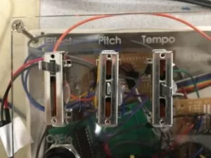
- 3 sliding potentiometers
- Protothreads library (pt_cornell_1_2.h)
Introduction
Our final project for ECE 4760: Digital Design Using Microcontrollers is a portable keyboard digital synthesizer using the PIC32MX250F128B microcontroller. The PIC creates various sound effects using direct digital synthesis (DDS) and frequency modulation (FM) synthesis which can be modified using user input on our keyboard’s easy-to-use user interface (UI). Our synthesizer is also capable of creating user-controlled digital effects. This project utilizes the ECE 4760 PIC32 Development Board by Sean Carroll to organize peripheral pins.
This project was designed primarily with portability and affordability in mind, allowing for curious minds to develop skills as a musician without spending large sums of money on musical equipment. Our synthesizer can easily fit in any standard size backpack.
High Level Design
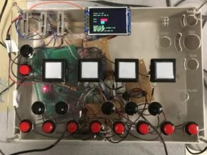
The synthesizer consists of a three major components: a keyboard interface of pushbuttons connected to a MCP23017 port expander, adjustable effects with peripherals directly connected to the PIC, and software for sound synthesis handled by the PIC. To allow for a clear UI, we use the Adafruit TFT LCD Display Model 1480 to display the current effects settings.
We generate sound with DDS and FM synthesis in our program’s interrupt service routine (ISR) using two sine tables as a reference for sound. Once the synthesis algorithms are complete, the ISR outputs the audio signal through an SPI connection to the MCP4822 digital-to-analog converter (DAC). This sound can be heard through any standard 3.5 mm phone connector. Software for our project also organizes the reads of peripheral inputs with the use of the protothreads library, pt_cornell_1_2.h. These threads include reading from the port expander, reading from the PIC’s peripheral pins, and recording sound for looping functionality.
Our keyboard interface consists 13 push buttons, which we formatted to appear as a C-to-C octave on a traditional piano, with red push buttons representing the white keys and black push buttons representing the black keys. We decided to use the port expander as a practical solution to the shortage of ports available in the PIC.
The synthesizer also contains four push buttons designed to toggle digital sound effects. Once again, to reduce the number of peripheral pins used on the PIC, we connected these buttons to the PIC using a the CD4051B analog multiplexer. These buttons are used to control flanging, FM synthesis, DDS, sound looping, and note sustaining effects. There are two additional buttons for modifying the parameters of digital effects controlled by sliding potentiometers that are connected to the PIC’s internal analog-to-digital converter (ADC). One of these two buttons cycles through the effects and the other enters in the modified effect values based on the potentiometer readings.
Hardware Design
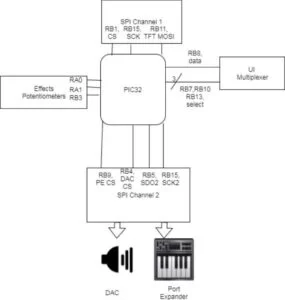
The peripherals used by our project include the DAC, port expander, and TFT screen, all of which were communicated with using SPI. We use the 12-bit DAC to generate the synthesizer’s sound. The base of our hardware design was Sean Carroll’s large development board, which came with pre-wired connections between certain PIC32 GPIO pins set up as SPI chip selects and serial data output pins, the TFT, the DAC, and the port expander.
Our hardware design when it came to the physical user interface was constrained by the large number of inputs into our system (13 keyboard push buttons, 6 effects push buttons, and 3 effects potentiometers). We could have potentially cut down on the number of system inputs by using an external keyboard or by combining the potentiometers. In the former case, we decided not to do so in order to make our system more compact and self-contained; in the latter case, combining potentiometers would remove the ability to simultaneously modify some parameters.
The PIC32 only has two SPI channels; however, we need to communicate with three devices. In order to do so, we used SPI channel two to communicate with both the port expander and the DAC. When the port expander is read and initialized, the program enters a critical section in which the DAC cannot communicate with the SPI. This ensures that the two devices sharing one SPI channel do not interrupt each other during their respective critical sections. For more about this, please see the software design section.
Peripheral Inputs
| Purpose | Pin |
|---|---|
| Effects Potentiometer | RA0 |
| Pitch Potentiometer | RA1 |
| Looping Tempo Potentiometer | RB3 |
| Mux Select A | RB7 |
| Mux Select B | RB10 |
| Mux Select C | RB13 |
| Mux Output | RB8 |
| Port Expander SPI MISO | RA4 |
| TFT D/C | RB0 |
| TFT-LCD SPI Chip Select | RB1 |
| TFT Reset | RB2 |
| DAC SPI Chip Select | RB4 |
| DAC + Port Expander SPI MOSI | RB5 |
| Port Expander SPI Chip Select | RB9 |
| TFT MOSI | RB11 |
| TFT SPI Sclock | RB14 |
| DAC/Port Expander SPI Sclock | RB15 |
| Keyboard Push Buttons | RY0-RY6, RZ0-RZ5 |
It should be noted that the ECE 4760 PIC32 Development Board has a port labeled “DACA,” which is used to output sound to the phone connector.
Keyboard Circuit
There were three kinds of circuits used in the user interface: push buttons interfacing with the port expander, push buttons used with the port expander, push buttons used with the multiplexer, and potentiometers.
When using the port expander, internal pull-up resistors can be enabled. As such, the button circuit becomes relatively simple:
When the button is pressed, the output is pulled down.
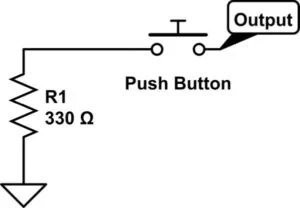
However, when using the multiplexer, internal pull-up resistors cannot be enabled, and so they must be implemented externally. The circuit is as follows:
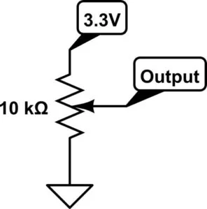
A potentiometer circuit uses the potentiometer’s variable resistance to modify the voltage of the input to the PIC32’s ADC. The circuit is shown as follows:
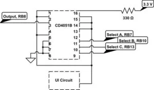
Multiplexing
We used the TI CD4051B, an 8:1 3-bit analog multiplexer, to connect 8 peripheral bits to RB8 on the PIC. We configured the three select bits, A, B, and C, to be written by RB7, RB10, and RB13 respectively. Table 2 describes the purpose of each mux input, the appropriate connections, and select line codes.
| Purpose | Mux Pin | Mux Channel | ABC |
|---|---|---|---|
| Flanger | 13 | 0 | 000 |
| FM Synthesis | 14 | 1 | 100 |
| Sustain | 15 | 2 | 010 |
| Cycle Button | 1 | 4 | 001 |
| Enter Button | 5 | 5 | 101 |
| Repeat Button | 2 | 6 | 011 |
The multiplexer itself had to be powered and its disable and VEE pins both had to be set to ground. The following diagram shows the circuit diagram.
Software Design
Code for this projected was written entirely using the C programming language. We wrote two files for this project, main.c and synth.h. The main program implements all of our functions and threads and the header file specifies all the function definitions for our program.
An important component in the interaction between hardware and software comes when reading from and writing to SPI. Since the PIC is connected to both the port expander and the DAC via SPI, critical sections must be used during every SPI operation to ensure mutual exclusion of the operations.
Program Listing
Code for this projected was written entirely using the C programming language. We wrote two files for this project, main.c and synth.h. The main program implements all of our functions and threads and the header file specifies all the function definitions for our program. For more about these files, please see our commented code in appendix B.
Sound Synthesis
Our program’s ISR is responsible for writing sound signals to SPI. It handles direct digital synthesis (DDS) by incrementing phase_accum_main by phase_incr_main; DAC_data then gets a value from the sine look up table located at index phase_accum_main>>24. Phase_incr_main is defined as
There are three additional effects that can be applied to the synthesizer: FM synthesis, flanging, and the modification of decay and attack times. FM synthesis creates a more “twangy” sound, flanging adds a reverb effect, and decay and attack times modify the exponential ramp up and down of notes.
Mathematically, FM synthesis is implemented by phase shifting the sinusoidal signal by a sinusoidal amount:
In order to implement FM synthesis, there are corresponding phase_accum_fm and phase_incr_fm variables for each note; phase_accum_fm is incremented exactly the same way as phase_accum_main. Phase_incr_fm will always be proportional to phase_incr_main; when modifying FM parameters, the user can changes that proportion.
Flanging creates a reverb effect by mixing the sound with a slightly time-delayed signal of itself; the delay does not exceed 20 ms. This delay is itself varied linearly in a sawtooth manner. When flanging is turned on, the signal to the DAC is
When users modify the flanging parameter, they modify how quickly the delay moves from maximum delay to minimum delay. Flanging is implemented using a circular buffer; every value that is output to the DAC is stored in this buffer until it is overwritten by a signal a fixed number of interrupt cycles later. A delayed signal is generated by reading values from the buffer corresponding to the amount of desired delay.
Decay and attack times control how sound down and up to and from zero. We implemented exponential decay and attack algorithms; using Euler integration, these are simply represented as
where the decay and attack rates are less than one. Generally, the attack_rate parameter is low (creating a fast rise) and the decay_rate parameter is high (creating a slow decay). There are also decay and attack rates associated with the amplitude of the FM phase shift mentioned earlier, although these are fixed and cannot be modified by the user.
The user can also turn on a sustain mode in which decay does not start until the user releases the key. This can be compared to the difference between a piano (sustain is off) and an organ (sustain is on).
Button Reading
There are two types of buttons in this project: keyboard buttons and effects buttons. The fundamental difference between reading these buttons in software comes their connections to the PIC. All of the buttons used for the keyboard are connected to the port expander, while all the buttons used for sound effects are connected to an analog mux which is directly connected to one of the PIC’s peripheral pins.
The keyboard buttons must be read from the SPI connection between the PIC and the port expander. The read_buttons thread defines the keyboard buttons as detailed in table 1. As mentioned above, critical sections must be used when defining and reading the ports in order not to interfere with communication with the DAC. Once configuration is complete, the thread polls the port expander ports to detect which button has been pressed. As the port expander consists of two ports, each must be read separately and concatenated using bit shifts and bit-wise ORs. It is determined if an individual button has been pressed by reading a certain bit from the resulting 13-bit number.
The effects buttons are read by the thread, read_mux. This thread polls each input to the mux by writing the appropriate select bits to the mux and reading the output of the mux given an appropriate select signal. These connections and effects are defined in table 1. It is necessary to have the thread yield for a few milliseconds between writing the select bits and reading the output; if this is not done, the mux will read an output that had an old or undefined select signal written to it. We used a 5 millisecond yield to remedy this.
Sound Recording
In order to record sounds, there are two arrays. One array keeps track of the time of each button press and release, and another array keeps track of which button was pressed. If the fourth press or release was of button five at time 100, button_pressed[4] would be 100 and button_press_ID[4] would be 5.
To replay sounds, the system reads these two arrays. The replay protothread loops through the button_pressed array, yielding for the difference between consecutive entries in the array in order to create proper timing. Then, the protothread reads what the ID in button_press_ID is and toggles that button; as each entry in button_pressed is a toggle, there is no need to keep track of whether the button is toggled on or off.
Effects Tuning
Our code reads values from three potentiometers that are connected to the PIC’s internal ADC to tune effects parameters: pitch, effects, and tempo tuning for the synthesizer’s looper. These connections are stated in table 1 and the ADC configuration is stated in table 3. To change pitch, our software directly reads the value from the pitch potentiometer and uses the value read to scale the frequencies used in sound synthesis. To change looping tempo, our program directly reads the value from the tempo potentiometer and multiplies the yield time in the repeat mode by the tempo parameter.
The effects potentiometer can be used to manipulate various effects. These adjustable effects are FM synthesis, flanging, attack speed, and decay. You can control which parameters are being modified using the two buttons labeled cycle and enter. The cycle button puts a selection cyclically onto one of the 4 parameters displayed on the TFT and the enter button confirms the parameter values used in computation. The connections for these buttons are defined in table 1.
User Interface
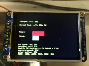
Our project’s UI allows for easy control over our synthesizer’s set up parameter by displaying the state of all the controllable parameters on the TFT along with which parameter is being modified with the effects potentiometer. The screen displays all parameters (except for tempo and pitch scaling) by showing their state (on/off) and their raw value read by the PIC (0-255 for digital inputs and 0-1023 for the analog inputs). We display tempo and pitch scaling using two rectangles with dynamic lengths to graphically show the relative intensity of scaling.
Functions
adc_config(void)
This function configures the PIC’s analog to digital converter. It begins by closing the ADC to make sure it is off prior to configuration. Then, it configures the ADC to sample AN0 (RA0), AN1 (RA1), and AN5 (RB3). The function to configure the ADC, OpenADC10() has many configuration details, so five parameter macros were defined to clean the code. These parameters are detailed in table 3. Once configuration is complete, the function can properly enable the ADC.
| PARAM1 | ADC_FORMAT_INTG16 | Result output format (16 bit justified) |
|---|---|---|
| ADC_CLK_AUTO | Conversion trigger source | |
| ADC_AUTO_SAMPLING_ON | Auto sampling select, set on | |
| PARAM2 | ADC_VREF_AVDD_AVSS | Voltage Reference |
| ADC_OFFSET_CAL_DISABLE | Offset calibration mode, disabled | |
| ADC_SCAN_ON | Scan selection, set on | |
| ADC_SAMPLES_PER_INT_3 | Number of samples between interrupts. | |
| ADC_ALT_BUF_OFF | Buffer mode select, set off | |
| ADC_ALT_INPUT_OFF | Alternate input sample mode select, set off | |
| PARAM3 | ADC_CONV_CLK_PB | Conversion clock is derived from systems clock |
| ADC_SAMPLE_TIME_15 | ADC sample time | |
| ADC_CONV_CLK_Tcy | Conversion clock select | |
| PARAM4 | ENABLE_AN0_ANA | Enable analog inputs |
| ENABLE_AN1_ANA | ||
| ENABLE_AN5_ANA | ||
| PARAM5 | SKIP_SCAN_ANX | skips scanning for pin x* |
*Note: PARAM5 contains SKIP_SCAN_ANX for all channels except the ones we desire to sample. That is, skip scan for all pins except AN0, AN1, and AN5. See main.c code in appendix B for more on PARAM5.
main(void):
The program’s main function sets up SPI, the TFT display, interrupts, timing, protothreads, and schedules appropriate tasks. It first opens timer2 with prescalar 1:4 and a period of 508 cycles. This was done to create a sample frequency of 20 kHz, which was sufficient to both reach the desired noise rejection, and slow enough to not overwork our processor. We choose a prescalar of 1:4, instead of a prescalar of 1:1 and a period of 508 cycles, because we had better results with the 1:4 prescalar. The look up tables for DDS, FM synthesis, and looping are also defined here. For SPI communication, RB5 get’s SDO for both the DAC and the port expander.
Results
We tested the functionality of each sound effect and repeat mode individually. Apart from conventional debugging, we also tuned the parameters of the sound effects to produce the sounds that we found to be subjectively the most aesthetically pleasing; these became user setpoints. We also used the oscilloscope to debug the signals that were produced by the DAC.
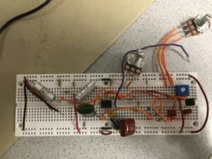
The bulk of testing took place when we debugged our hardware and circuitry. Shorts in push button circuits would cause the PIC to reset if the button were pressed, which was a common error that could be debugged using a multimeter to test for resistances.
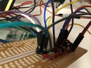
As can be seen in our demonstration video, all implemented features of the system work properly, indicating basic reliability on a hardware and software level. However, the product is only a first draft. The most obvious area for improvement would be better hardware integration: we did not anticipate the amount of wiring and soldering needed to implement our circuit, and so the final product was messy, hard to debug, and prone to unpredictable hardware bugs if jostled. We could also implement a more polished UI and additional sound effects, including possible analog effects like a guitar tone stack or different DDS tables such as square waves or sawtooth waves.
Conclusion
We were able to successfully build a portable digital synthesizer with the PIC32. The experience of building this project was extremely rewarding, allowing us apply our ECE skills developed over our undergraduate experience to build something relating to our passion for music.
While developing this project, we learned how critical it is to have proper hardware functionality during the early stages of development. We began work on this project focusing primarily on sound synthesis in software, believing this would be the hardest part of our project, pushing hardware development to later stages. Once we finished software implementation, we moved began to implement the hardware we designed. This turned out to be a much more difficult task than anticipated.
The circuits we designed were all relatively straight-forward, consisting almost entirely of push buttons, and potentiometers connected to the PIC’s peripheral pins. The issue is that there was a large amount of hardware, which was difficult to organize well in the enclosure we purchased in our project. This resulted in many hours of debugging circuitry until we finally had everything functioning.
The original design of our project contained two analog circuits designed for analog distortion and a tone stack to further manipulate our sound. We unfortunately had to discard these designs due to time constraints.
Standards
No standard was involved in this project.
Intellectual Property Considerations
We drew an early version of the design for this project from the project “PIC32 MIDI Synthesizer” by Steven Blasberg, David Landy, and Marshall Mucasey. However, during the development process, we decided to create our own keyboard interface rather than using the MIDI standard in the interest of portability and gaining more hands-on hardware building experience. A major difference in our projects is that keyboard is capable of playing multiple notes simultaneously. Other differences are in sound synthesis, sound effects, and user interface.
All of our source code in main.c and synth.h was written by members of our group. All libraries such as the protothreads and port expander libraries were used with permission of the instructor. Our code is open-source and can be published in any magazine or journal. No design was reverse-engineered to create this project. We delt with no patent or trademark issues. No non-disclosure agreements were signed.
Ethical Considerations
We designed and implemented this project in accordance with the IEEE Code of Ethics. This project does not violate any of the standards mentioned in the code. Our project presents no danger to any user unless it is modified. None of our team members have any potential conflicts of interests with any technology used; our design is open source, so we will not be profiting from it. Our project can be a low cost way to educate people about music. During development, we were always respectful to each other, course staff, and other groups using the lab space. If a group was experiencing similar bugs to ones we encountered and fixed, we were ready to provide them with help. At all times, we understood each other’s strengths and weaknesses as engineers and assigned tasks appropriately. If one of us did not have a particular skill that was necessary to complete a task, we would take time to carefully learn that skill before applying it to the project. At no point during this project’s development were any of our team members approached with a bribe of any kind, nor did we ever even consider to seek one out. We believe it is important to create a bridge between art and technology in order to enrich the human experience and we hope that this project contributed to this.
Legal Considerations
This project is not subject to any legal considerations.
Acknowledgements
We would like to thank Professor Bruce Land and our TAs, Samir Durvasula, Brian Clark, Brian Gross, Shaan Shetty, and Yunqi (Mark) Zhao for their continuous help during the development of this project. Without their support, this project would not have been possible.
Source: PIC32 Digital Synthesizer
- How does the synthesizer generate sound?
The program uses Direct Digital Synthesis and FM synthesis within an interrupt service routine to create sine waves from lookup tables. - What hardware is used to expand the available ports on the PIC?
A MCP23017 port expander is used to connect the 13 keyboard push buttons due to port shortages. - Can users modify sound parameters in real time?
Yes, three sliding potentiometers allow users to tune pitch, effects, and looping tempo while connected to the internal ADC. - How are the effects buttons connected to reduce pin usage?
Analog push buttons for effects are connected to the PIC using a CD4051B analog multiplexer. - What interface is used to display current settings?
An Adafruit TFT LCD Display Model 1480 displays effect states, raw values, and graphical representations of scaling. - Does the device support recording and replaying sounds?
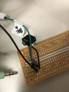
Yes, the software records button press timing and IDs into arrays to loop and replay sequences later. - What type of output connector is used for audio?
The system outputs audio through a standard 3.5 mm phone connector via the DAC. - How is the sampling frequency determined?
The system uses Timer2 with a prescalar of 1:4 and a period of 508 cycles to achieve a 20 kHz sample frequency. - What limits the delay time in the flanging effect?
The flanging delay does not exceed 20 ms and is varied linearly in a sawtooth manner using a circular buffer. - Are there any external libraries required for the code?
The project utilizes the protothreads library specifically pt_cornell_1_2.h to manage input reading and sound recording threads.