Summary of PIC18F452 CCS C RF HUMIDITY TEMPERATURE CIRCUIT (ADDITION TO CALENDAR, CLOCK)
This project is a wireless weather station featuring a transmitter and receiver circuit controlled by PIC18F452 and PIC16F84 microcontrollers. It monitors temperature, humidity, and pressure using specific sensors and displays data on an LCD with calendar and clock functions. The system uses RF modules for communication, stores history in EEPROM, and operates on battery power with sleep modes to conserve energy.
Parts used in the PIC18F452 CCS C RF Humidity Temperature Circuit:
- PIC18F452 Microcontroller
- PIC16F84 Microcontroller
- MPX4115 Pressure Sensor
- TC77 SPI Temperature Sensor
- H1 Humidity Sensor
- RX + TX433 Wireless RF Modules
- DS1307 Real-Time Clock
- 24C256 I2C EPROM
- LCD Screen
- 3-Button User Menu Interface
Feature a very high level transmitter and receiver circuit consists of two parts of a project are provided with the main control PIC18F452 PIC16F84 sensors are connected to the transmitter circuit based on the information received from sensors on… Electronics Projects, PIC18F452 CCS C RF Humidity Temperature Circuit (addition to calendar, clock) “microchip projects, microcontroller projects,
Feature a very high level transmitter and receiver circuit consists of two parts of a project are provided with the main control PIC18F452 PIC16F84 sensors are connected to the transmitter circuit based on the information received from sensors on the lcd screen is displayed as text and graphical
MPX4115 pressure sensor TC77 SPI temperature sensor H1 humidity sensor wireless RF communication RX + TX433 modules used also DS1307 RCT and 24C256 i2c EPROM entegreleri in the project used the software CCS C (PCWH CCS compiler) prepared with source c code eagle pcb schema files located in the heat, humidity , pressure calibration settings explained.
This project uygulamasa your hardware, software, a very good example for the use of the sensor can be integrated
Pressure reading, relative humidity, temperature and away off the outer display.both Celsius or Fahrenheit & mbar / hPa or mm Hg supported weather station. With calendar and clock. Easy three button user menu. 42-hour history display (curve). Automatic memory and to show all the high and low values. PIC 18F452 4 MHz, works in sleep mode to save power. Sensors is only open when needed ..
PIC18F452 RF HUMIDITY TEMPERATURE PROJECT
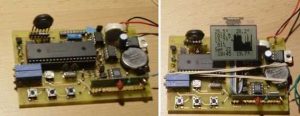
Now this was a great project! I’ve tried various LCDs currently testing all the sensors had to be a complete, wireless communication has to be perfect. Still, here’s the result: I hope you enjoy it! Circuit 9V battery can power a small, but more want to get a good pair of AA-size batteries. 6-pack will last a few months. Consumption for base station and about 8 9 mA in sleep mode when enabled only 2 to 3 m (LCD remains are.) Transmitter is slightly less.
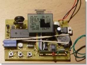
Receiver (base station) is active for 5 seconds and then goes to sleep for 45 seconds. The transmitter takes a nap every 30 seconds or so. In the Menu mode “buttons” menu pushing (what a name is entered?) For 1 second. Scan and changes the value of “min” and “plus” buttons are made. When in normal mode (for example, in the picture above) and “minute” and “plus” buttons with different backgrounds can browse. All of these controls if the processor is in sleep mode wakes up will be.
In the left hand side we have the LCD (top-down 🙂 Return Temperature, Relative Humidity, Calendar and Clock in the outside temperature, pressure,. Correct: Last 42 hours of high-value, bar chart, histogram (right most recent value), is a low value. All sensors are read and the LCD (left side) is updated every 50 seconds. The histogram on the clock (for example, 10h00, 17h00, 22h00, …). All data is stored in EEPROM and power up when installed will be updated. In case of a power outage (or), no data (nor will be the date) battery replacement lost.
PIC18F452 CCS C RF Humidity Temperature Circuit schematic pcb ccs c source code files
FILE DOWNLOAD LINK LIST (in TXT format): LINKS-6568.zip
Source: PIC18F452 CCS C RF HUMIDITY TEMPERATURE CIRCUIT (ADDITION TO CALENDAR, CLOCK)
- How does the system save power?
The PIC18F452 works in sleep mode, keeping sensors open only when needed. - What units of measurement are supported?
The device supports Celsius or Fahrenheit for temperature and mbar/hPa or mm Hg for pressure. - How often are sensor readings updated?
All sensors are read and the LCD is updated every 50 seconds. - What happens if there is a power outage?
Data and date are lost if the battery is replaced during a power outage. - How long does the battery last?
A 6-pack of AA-size batteries will last a few months. - What is the sleep cycle of the base station?
The receiver is active for 5 seconds and then sleeps for 45 seconds. - Can users access historical data?
The system displays a 42-hour history curve showing high and low values. - How do you navigate the menu?
Pushing buttons for 1 second enters menu mode to scan and change min or plus values.