Summary of PIC18F2550 DEVELOPMENT BOARD CIRCUT USB BOOTLOADER PCB
This article describes a PIC18F2550 application/development board with USB bootloader support, featuring USB communication, 24Cxx I2C EEPROM, ICSP programming with LVP option, 5V/1A regulated supply, 20 MHz crystal, and configurable pinheaders for I/O and peripheral selection. It highlights jumpers for routing B6/B7, B0/B1, and USB-related pins, power/reset functions, and on-board terminals for easy PCB or perfboard mounting. Files (Proteus ISIS/ARES and project ZIP) are provided by the author.
Parts used in the PIC18F2550 Application Board:
- PIC18F2550 microcontroller
- 24Cxx EEPROM (I2C)
- 20 MHz crystal
- 6-15V power supply input (connector)
- 7805 5V voltage regulator (1A)
- USB connector
- ICSP header
- Pin header I/O terminal system
- Jumpers J1, J2, J3, J4, J5, J6, J7
- Capacitors C4 and C5
- Power LED
- Reset (MCLR) circuit/pull-down or pull-up
- Power out terminal (GND and +V, +5V output)
Unlike other applications that attempt PIC18F2550 development board “USB bootloader” option for the project for which you want to apply with the PIC18F2550 keep a circuit will provide great convenience for. PIC18F2550 Application Board… Electronics Projects, PIC18F2550 Development Board Circut USB Bootloader PCB “pic development board, pic18f2550 projects, ”

Unlike other applications that attempt PIC18F2550 development board “USB bootloader” option for the project for which you want to apply with the PIC18F2550 keep a circuit will provide great convenience for.
PIC18F2550 APPLICATION BOARD PCB
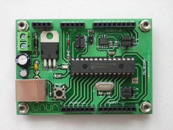
Hardware; PIC 18f2550 I/SP microcontroller., 24Cxx EEPROM (I2c communication with), 20 MHz crystal., 6-15V power supply input., 5V 1A regulated output., USB support., ICSP programming, Pin header I/O terminal system
General features and usage
1-USB: USB support is the most important feature of self PIC 18f2550 aygün surgical instruments carried out. In this way, you can have a quick communication with your computer via USB.
2-24Cxx EEPROM with I2c serial communication protocol, communicate with each other on the card: an eeprom.
3-ICSP programmer with ICSP support from microdenetleyicinizi over a: removing the card on the program.
4-5V regulated: regulate the IC Card on the 7805 5v supply is provided through microdenetleyicinizin.
5-ICSP-jumpers J1 and J2 I/O with B6 and B7: ports on demand for ICSP programming or I/O port allows you the choice of using.
6-LVP: J3 jumper is inserted ICSP programming with low voltage mode programming. (Supports Low voltage programming for programmers.)
7-I2c – I/O: J4 and J5 jumpers B0 and B1 ports on demand through the I2c communication is the use of the eeprom or I/O port allows you the choice of using.
8-USB-I/O: J6 and J7 thanks to C4 and C5 ports on demand USB communication jumpers or the ability to use selection as I port.
9. Power Led: indicates whether the + 5v supply.
10-Reset: old Microdenetliyicinin foot pulls MCLR pulls back. Reset the reset is activated from the program.
11-Power Out Terminal: terminal 4 output. One of these 2 GND (negative), and others;
+ V is the same as the voltage is entered into clips on the card:.
+ 5V output voltage circuit is: (max. 1A)
12-Port I/O Terminal: terminal system in all ports with active Mikrodenetliyicinin pinheader is available.
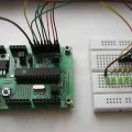
PIC18F2550 BOARD ICSP CONNECTION
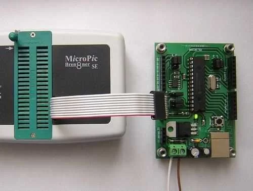
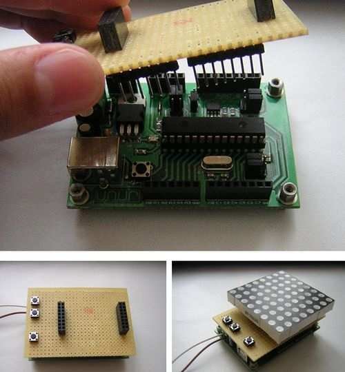
On-board supply and the I / O terminals to the top pcb mounting system is designed as a pinhead, according to the template established on their drawings printed circuit boards or perforated plate circuits that can operate easily.
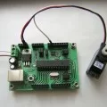
author: Cenk Cemil UNUR [email protected] – Bootloader PIC18F2550 Circuit of the proteus isis, ares files and microchip software: pic18f2550-development-board-circut-usb-bootloader-pcb.ZIP
- What is the main communication feature of the PIC18F2550 application board?
USB support provides quick communication with a computer. - Does the board support external EEPROM?
Yes, it includes a 24Cxx EEPROM communicating via I2C. - How is the board programmed?
The board supports ICSP programming and has jumpers for ICSP use. - Can the board use low voltage programming?
Yes, inserting jumper J3 enables low voltage programming mode. - How is the microcontroller powered and regulated?
The board accepts 6–15V input and uses a 7805 regulator to provide 5V up to 1A. - Are I/O pins accessible for external connections?
Yes, all microcontroller pins are available on a pinheader I/O terminal system for easy mounting. - What do jumpers J1 and J2 do?
J1 and J2 select between ICSP programming or using B6 and B7 as I/O ports. - What do jumpers J4 and J5 control?
J4 and J5 allow choosing B0 and B1 for I2C communication with EEPROM or as general I/O. - How are USB pins used as I/O?
Jumpers J6 and J7 with C4 and C5 enable selecting USB communication or using those pins as I/O ports. - Is there an indicator for power status?
Yes, a Power LED indicates the presence of the +5V supply.