There a few years, PC began to be powerful enough to réaliserde software synthesis. For my part, I discovered the real time software synthesis with ReBirth on my Pentium 166MHz MMX. Of course, software synthesis exist on the PC,… Electronics Projects, PIC17C77 Midi Control Circuit MC14067 “microchip projects, microcontroller projects, pic assembly example,
There a few years, PC began to be powerful enough to réaliserde software synthesis. For my part, I discovered the real time software synthesis with ReBirth on my Pentium 166MHz MMX. Of course, software synthesis exist on the PC, such as Virtual Waves, but the arrival of real-time creates a turning point for me anyway. At the same time, he created a new need.
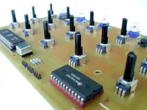
to remain general, the main objective is to provide MIDI signals function 15 knobs. More specifically, the 15 faders knobs will be scanned by a multiplexer, itself controlled by a microcontroller Microchip PIC16C77 which will at the same time take care to do the AD conversion. As soon as he finished the conversion to digital, it compares the value obtained with the old value that was stored in memory, and if it has changed (so if the knob was turned) it will transmit the new value in accordance with the MIDI protocol. Three bytes are transferred (channel number & type ‘Control Change’ – controller number – value of the controller). So much for the outline. In fact, the program is a little more complex, for example, I use a small anti-oscillation based subtraction (and passing 8 bits to 7 bits) routine which avoids having a saturation due to canal du midi inadvertent transmission of a value or the last bit is sometimes read 1 0 now to read by the converter. In the same vein, I also use a routine reassignment numbers controllers, which simplifies the design of CI. But I suggest you look at the sources for more information.
– The second objective is to use the 5 switches / leds down the desk to send midi commands (note, control …) on the one hand and position the LED according to a given Noon ‘ other. To perform these operations, two chips are used, a multiplexer and a state memory – 74HC4051 & 74HC259. Unfortunately, I never finished the software implementation of these features … The fans!
Source: m.bareille.free.fr PIC17C77 Midi Control Circuit MC14067 alternative link:
FILE DOWNLOAD LINK LIST (in TXT format): LINKS-1668.zip