PIC16F877 microcontroller with LCD also shows the engine speed encoder circuit. These and the interrupt routine of the main program flow chart is a flow chart. PORT in the main program and is defined PORTB aspects. Then the program… Electronics Projects, PIC16F877 LCD Motors Speed indicator Encoder Circuit “microchip projects, microcontroller projects, pic16f877 projects,
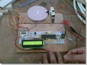
PIC16F877 microcontroller with LCD also shows the engine speed encoder circuit. These and the interrupt routine of the main program flow chart is a flow chart.
PORT in the main program and is defined PORTB aspects. Then the program enters an infinite loop and is expected to come from the encoder pulse. Each pulse from the encoder when the “count” variable is incremented by one.
An interrupt routine to get every 66 ms. LCD is prepared to start the program again. Then every 66 ms to a motor speed is calculated and printed peers. Again using our program the ADC is adjusted by the motor speed PWM. PWM is already indicated in the flow chart.
PIC16F877 MOTORS SPEED INDICATOR ENCODER SCHEMATIC
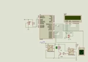
Encoder project Files isis simulation schematic and pic c source code files
FILE DOWNLOAD LINK LIST (in TXT format): LINKS-5596.zip
Source: PIC16F877 LCD MOTORS SPEED INDICATOR ENCODER CIRCUIT