Summary of PIC16F84A software UART (bit banging) code and Proteus simulation
This article details implementing software UART (bit-banging) on the PIC16F84A microcontroller using C language and the HI-TECH compiler. It explains configuring baud rates, crystal frequencies, and pin assignments (RA0 for TX, RA1 for RX) to enable serial communication with a PC. The code echoes received characters and was verified via Proteus simulation.
Parts used in the Software UART on PIC16F84A:
- PIC16F84A microcontroller
- External crystal oscillator
- MPLAB IDE
- HI-TECH C compiler
- Proteus simulation software
- Serial adapter
- Virtual terminal
This post provides the software UART (Bit Banging) code for PIC16F84A microcontroller (e-g to connect PIC controller with PC using serial adapter). As we know, PIC16F84A microcontroller doesn’t have built in UART module, so we can create UART functionality in it’s software. This post provides the details of how to program software UART functionality in PIC16F84A. This code is written in C language using MPLAB with HI-TECH C compiler. You can download this code from the ‘Downloads‘ section at the bottom of this page.
It is assumed that you know how to blink an LED with PIC16F84A microcontroller. If you don’t then please read this page first, before proceeding with this article.
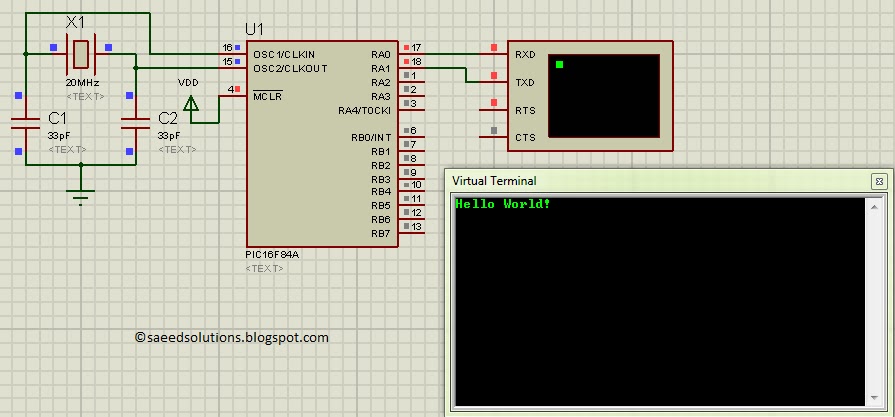
The result of simulating the code in Proteus is shown below.
In the above figure, UART baudrate is currently set to 1200 bps, but you can change it to your desired value. RA0 pin is being used as TX pin and RA1 pin is the RX pin of the software UART. Code is written in such a way that PIC16F84A echos back whatever character is sent to it. Hello World! was typed in the virtual terminal after the start up of the simulation in Proteus and PIC16F84A echoed it back.
Code
The code used to set different properties of UART is shown below. (From Software_UART.h file)
In the above figure, _XTAL_FREQ is defined to be 20000000, which is the external crystal frequency used with this PIC16F84A. If you change the crystal (e-g by attaching an external crystal of different frequency) then you will need to change _XTAL_FREQ value as well. For example, if 12MHz external crystal is used, then _XTAL_FREQ should be defined as 12000000 in the above code.
Similarly, you can define Baudrate for the UART, in the above figure it is defined to be 1200 bps. Since this is a software UART, that is why when you increase Baudrate , then bit error rate for UART also increases drastically. You should increase crystal value to reduce UART bit errors. For example to use a Baudrate of 4800, you should use a crystal of at least 20MHz. DataBitCount is defined to be 8, which means this UART will use one starting bit, 8 data bits and then one stop bit. There is no parity bit and no flow control mechanism.
RA1 and RA0 pins are being used for the UART. You can easily change these pins, for example by defining UART_RX to be RA3 and UART_RX_DIR to be TRISA3, RA3 pin will become UART RX pin. Similarly you can change UART TX pin if required.
The code for main function is shown below.
Downloads
Software UART code for PIC16F84A was compiled in MPLAB v8.85 with HI-TECH C v9.83 compiler and simulation was made in Proteus v7.10. To download code and Proteus simulation click here.
For more detail: PIC16F84A software UART (bit banging) code and Proteus simulation
- How can I create UART functionality on a PIC16F84A?
You can create UART functionality by writing software code known as bit-banging since the chip lacks a built-in module. - What pins are used for TX and RX in this project?
RA0 is used as the TX pin and RA1 is used as the RX pin. - Can I change the default baud rate settings?
Yes, you can change the baudrate value in the code, but increasing it may drastically increase the bit error rate. - What happens if I use a different crystal frequency?
If you change the external crystal frequency, you must update the _XTAL_FREQ value in the code to match the new frequency. - Does this UART configuration include parity or flow control?
No, this UART configuration uses one starting bit, 8 data bits, and one stop bit with no parity bit or flow control mechanism. - Is it possible to change the RX and TX pins?
Yes, you can easily change these pins by defining different port numbers like RA3 for both the UART_RX variable and its direction register. - What tools were used to compile and simulate the code?
The code was compiled in MPLAB v8.85 with HI-TECH C v9.83 and simulated in Proteus v7.10. - What is the recommended crystal frequency for a 4800 baud rate?
To use a baud rate of 4800, you should use a crystal of at least 20MHz to reduce UART bit errors.