Summary of PIC16F84 LINE FOLLOWER ROBOT PROJECT
This project describes a line-following robot using a PIC16F84 microcontroller. It detects black lines (approx. 7mm wide) using CDS sensors and standard 3V bulbs instead of infrared LEDs. The system controls left/right motors via Port B outputs (RB4, RB6) triggered by sensor signals on Port A (RA1, RA2). An external interrupt on RB0 manages motor operation for about 30 seconds, while an LED indicates state changes and a buzzer signal is routed through RB7.
Parts used in the Line Follower Robot:
- PIC16F84 Microcontroller
- CDS Sensors (5mm diameter)
- 3V Bulbs
- Twin Motor Gearbox
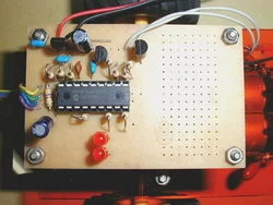
- Bull's-eye Half Board
- LEDs
- Buzzer
Line following robot is the thing to run on the line by controlling the motor of the left and right detected by light, such as infrared drawn in black (7m / m width or so) line. As illuminating the… Electronics Projects, PIC16F84 Line Follower Robot Project “microchip projects, microcontroller projects, pic assembly example, pic16f84 projects,

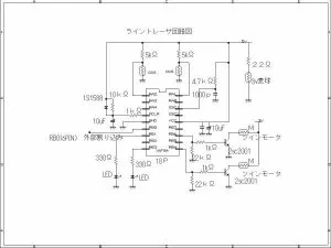
Line following robot is the thing to run on the line by controlling the motor of the left and right detected by light, such as infrared drawn in black (7m / m width or so) line. As illuminating the line, I put the light of the ordinary uses wheat balls of 3 volts instead of the infrared, we used (at the Akizuki) CDS with a diameter of 5m / m the sensor this time. The CDS ON motor twin motor gearbox controls the RB4, RB6 of port B sent to RA1, RA2 of port A of the PIC signal ON when out of the line, the signal OFF when applied to the line, and OFF. LED indicates the state.
Software is a thing of the ordinary, but is attached to the external interrupt RB0 port of B. Motor it indicates that you have entered the interrupt operation (about 30 seconds) LED stops flashing alternately once interrupt enters. The signal of the oscillation sound has placed it out of the RB7 of port B. These and there is not to the wiring, but so have been on board the bull’s-eye half board, you may want to experiment with a favorite circuit later. For example, I am such as to interrupt or light voice.
LINE FOLLOWER PICMICRO PROJECT
LINE FOLLOWER ROBOT SCHEMATIC
Source site: web1.incl.ne.jp Line Follower Robot Schematic pic assembly source code alternative link:
FILE DOWNLOAD LINK LIST (in TXT format): LINKS-5217.zip
Source: PIC16F84 LINE FOLLOWER ROBOT PROJECT
- How does the robot detect the line?
The robot detects the black line using CDS sensors illuminated by 3V ordinary bulbs. - What microcontroller is used in this project?
The project utilizes the PIC16F84 microcontroller. - How are the motors controlled?
Motors are controlled by sending signals from port B pins RB4 and RB6 based on sensor inputs. - What happens when an interrupt occurs?
When an interrupt enters, the LED stops flashing alternately and the motor operates for about 30 seconds. - Where is the oscillation sound signal placed?
The signal for the oscillation sound is placed at pin RB7 of port B. - What width line can the robot follow?
The robot is designed to run on a black line with a width of approximately 7mm.