Summary of PIC16C84 PICMICRO CONTROLLED CAPACITANCE METER CIRCUIT
This article details a PIC16C84 microcontroller-based capacitance meter featuring four measurement ranges and Auto/Manual modes. The device uses an LCD for displaying values in pF, nF, or uF, with features like zero-offset comparison and auto-ranging logic to ensure accuracy within 1%. The project includes assembly code (CMETERA.ASM) designed for the PIC16C84, utilizing specific integrated circuits for timing and counting functions.
Parts used in the PIC16C84 PICmicro Controlled Capacitance Meter:
- PIC16C84 Microcontroller
- 74HC390 Integrated Circuit
- 4011 Integrated Circuit
- NE555 Timer
- LCD Display
- Reset Switch
- Zero Switch
- UP Button
- DOWN Button
- Internal Relays
PIC16C84 and with other integrated circuits (74HC390, 4011, NE555) measuring devices with micro-controller can be an example to people who want to design pcb files available asm the schema The Capacitance Meter has 4 ranges. In Manual Mode each… Electronics Projects, PIC16C84 PICmicro Controlled Capacitance Meter Circuit “microchip projects, microcontroller projects, pic assembly example,
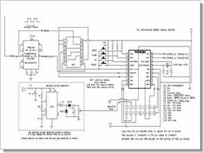
PIC16C84 and with other integrated circuits (74HC390, 4011, NE555) measuring devices with micro-controller can be an example to people who want to design pcb files available asm the schema
The Capacitance Meter has 4 ranges. In Manual Mode each range has an absolute minimum and maximum reading that corresponds to a count range from 0 to 16,777,215 counts. The extremes of each range are where the greatest error occurs, so in the Auto Mode we restrict the range to that portion where we will attain the greatest accuracy.
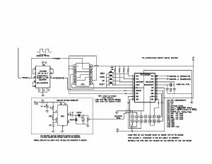
CAPACITANCE METER SCHEMATIC
CAPACITANCE METER PIC ASSEMBLY CODE
CMETERA.ASM
;        Fr. Tom McGahee's PIC CAPACITANCE METER
;
;                   Fr. Thomas McGahee
;             Don Bosco Technical High School
;                    202 Union Ave
;               Paterson, NJ  07502  USA
;
;               [email protected]
;                    (973)595-6655
;
;        permission granted for individual use
;
;                Microchip MPASM format
;       Specifically designed for PIC16C84. Skeleton file.
;

; note: set assembler to case-insensitive, except within strings using /c- option
;

;OPERATIONAL DESCRIPTION OF PROJECT


;the mclear (reset) switch causes a reset and return to autorange.
;the other three switches cause an immediate move to manual mode.
;zeroswitch causes most recent displayed reading to be used as
;a zero offset. this allows the user to compare two capacitors.
;a + or - sign is displayed to indicate relative value.
;hold key down until updating stops. upon release the
;current value will be displayed.

;first line of lcd displays a + or a blinking - sign in the first
;position. This indicates whether the current displayed value is
;higher or lower than the Comparison Value (normally 0). You may
;"zero-out" any value desired by pressing the ZERO button. This will
;cause the current value to be subtracted from all future readings.
;pressing the ZERO button also forces the unit into Manual Mode.
;you can return to Auto Mode by removing the capacitor and pressing
;the reset button, or by removing the capacitor and turning the
;power off and then on again.

;manual mode can also be entered by pressing either the UP or DOWN
;buttons. (hold button down until updating stops, then release).
;UP and DOWN are used to move from one range to another in Manual Mode.
;unit starts out in Auto Mode, and will automatically switch to the
;best (most accurate) range for any given capacitor. Auto Mode has
;built-in hysteresis to prevent the capmeter from constantly
;cycling between ranges.

;the second position on the first line is sometimes occupied by a
;blinking letter "M". This indicates that you are in Manual Mode,
;and that the Auto Mode would have issued a command to go to a
;lower range. Obviously in Manual Mode you want to be able to
;change capacitances being measured, and at such a time the value
;being measured will temporarily go to zero, causing this feature
;to kick in.

;the rest of the first line is allocated to the display of the current
;count. internally a 24 bit counter allows the accumulation of counts
;up to 16,777,216. In Auto Mode the AutoRanging kicks in at around
;524,288 to range UP, and below 32,768 it shifts DOWN. There are 4
;ranges. In the lowest range it allows a display of from .00 pf to
;5,242.88 pf. range 2 ranges from 4,096 pf to 524,288 pf. range 3
;ranges from .4096 uf to 52.4288 uf. range 4 ranges from 32.768 uf
;to 16,777.216 uf.

;in Manual Mode you can generate counts from 0 to 16,777,216
;but the accuracy outside the above specified ranges can then
;have an error greater than 1%. use autoranging for maximum
;accuracy. use Manual Mode when using the Comparison feature
;or when you don't want the unit to AutoRange. AutoRanging to zero
;always causes the unit to go to range 1 for zero. then when you
;attach a new capacitor it may take a few seconds before AutoRanging
;detects an aout-of-range condition and responds. by the way, to
;speed up from such zero excursions I have implemented the UP Range
;portion of the AutoRange so that it always goes to range 4. I do
;this because it is always quicker to down range than it is to up
;range. there is method to my madness!

;values are displayed properly positioned over the value identifiers
;such as uf nf and pf. a space is provided between each set of 3
;digits to reflect standard engineering notation. partial number
;sets are padded with _ to the right. numbers have leading zeros
;suppressed up to the decimal point. commas are added where they are
;appropriate.

;note that sometimes many more digits are displayed than the accuracy
;warrants. in general you can trust the first 3 digits to be right
;on. the 4th digit is normally accurate +/- 1 count. additional
;digits are displayed not for additional accuracy, but simply because
;they are useful for watching variations due to temperature, etc.,
;and they are useful in matching two or more capacitors.

;basic accuracy is 1% or better within the AutoRanging values
;up to about 100 uf. by the time you get a measurement like
;16,000.000 uf the time to collect such a measurement has risen to
;almost 24 seconds. this causes the accumulated error to rise
;to a few percent.

;the first position on the second line will display a number from
;1 to 4. this represents the current range, where 1 is the lowest
;range. the middle section of the second line contains the uf
;nf and pf indicators, positioned directly below the numeric groups
;that they refer to. I chose to display more than one set of
;indicators so you can easily read something like:
;
;+     12,000.___
;2 fd  nf  pf A**
;
;as either .012 uf   12.000 nf    or  12,000 pf.

;after the uf/nf/pf indicators there is either an "A" or an "M"
;displayed as an indicator of either Manual or Auto Mode being
;active. this is followed by two locations that display an
;animated (moving) black box to indicate that a new count is
;in progress. this is replaced by ** to indicate that the
;on-screen count has just been updated. These asterisks will
;remain on-screen until the circuitry detects edge synchronization.
;then the flashing black boxes appear. to speed up the
;synchronization process I have separate routines for handling
;rising and falling edges.

;occassionaly you will see a message such as "OVER-RANGE!" when
;in the manual mode. if the number is still displayed, then this is
;just a cautionary warning that the displayed value lies outside
;the range where it can be guaranteed to be 1% accurate.
;if the message is the *only* thing displayed on the screen,
;then you have exceeded the 16 million count limit and really
;need to switch to a higher range.
;
;during AutoRanging a quick flash of the word "AUTORANGING" will
;appear, and you may hear a click from the internal relays. some
;ranges switch without the click sound because they are using
;external counters to switch ranges.

;a note of caution when using Manual Mode: if you have set the
;device to operate in Comparison Mode by pressing the ZERO
;button, this zero comparison value will be retained *for the
;current numbered range* even if you move to another scale.
;before moving to another scale it is therefore a good idea
;to remove the cap being measured and press the ZERO button to
;re-zero the scale. if you don't do this, then the next time
;you return to that range the Comparison value will again
;be in effect. there is nothing wrong with bridging a comparison
;over two different ranges. if you want to do that, you
;have to press the ZERO button at *each* range you want to
;perform the comparison on.

;because the ZERO button automatically causes entry into the
;Manual Mode, you usually can't run Comparison Mode in
;Auto Mode. however, *if* you hit the reset button and have
;a capacitor attached, the reset auto-zero feature will
;cause the current cap value to be subtracted on *every* range.
;this works with values up to about 1 uf with no problem.
;larger values will cause overflow errors on the lower ranges
;and may therefore give erroneous readings. also note that the
;time required to perfom the auto-zero function increases
;with increasing external capacitance. if the cap value is more than
;a few uf then the auto-zero logic may cause the circuitry to
;cycle endlessly in an attempt to zero the lower ranges.
;if that happens, remove the capacitor and perform a reset.


;
; directives
;


;
; note: written in all lower case so case sensitivity doesn't matter.
; however: set assembler to case-insensitive, except within strings using /c- option
;

;
; directives
;


		list		p=pic16f84	;this directive must come first

; instead of using the [ include <16f84.inc> ] we have placed the contents of the
; microchip supplied include file below for documentation purposes.
;
; P16F84.INC  Standard Header File, Version 2.00    Microchip Technology, Inc.

; This header file defines configurations, registers, and other useful bits of
; information for the PIC16F84 microcontroller.  These names are taken to match
; the data sheets as closely as possible.

; Note that the processor must be selected before this file is
; included.  The processor may be selected the following ways:

;       1. Command line switch:
;               C:\ MPASM MYFILE.ASM /PIC16F84
;       2. LIST directive in the source file
;               LIST   P=PIC16F84
;       3. Processor Type entry in the MPASM full-screen interface
;==========================================================================
;
;       Verify Processor
;
;==========================================================================

        IFNDEF __16F84
           MESSG "Processor-header file mismatch.  Verify selected processor."
        ENDIF

;==========================================================================
;
;       Register Definitions
;
;==========================================================================

W                            EQU     H'0000'
F                            EQU     H'0001'

;----- Register Files------------------------------------------------------

INDF                         EQU     H'0000'
TMR0                         EQU     H'0001'
PCL                          EQU     H'0002'
STATUS                       EQU     H'0003'
FSR                          EQU     H'0004'
PORTA                        EQU     H'0005'
PORTB                        EQU     H'0006'
EEDATA                       EQU     H'0008'
EEADR                        EQU     H'0009'
PCLATH                       EQU     H'000A'
INTCON                       EQU     H'000B'

OPTION_REG                   EQU     H'0081'
TRISA                        EQU     H'0085'
TRISB                        EQU     H'0086'
EECON1                       EQU     H'0088'
EECON2                       EQU     H'0089'

;----- STATUS Bits --------------------------------------------------------

IRP                          EQU     H'0007'
RP1                          EQU     H'0006'
RP0                          EQU     H'0005'
NOT_TO                       EQU     H'0004'
NOT_PD                       EQU     H'0003'
Z                            EQU     H'0002'
DC                           EQU     H'0001'
C                            EQU     H'0000'

;----- INTCON Bits --------------------------------------------------------

GIE                          EQU     H'0007'
EEIE                         EQU     H'0006'
T0IE                         EQU     H'0005'
INTE                         EQU     H'0004'
RBIE                         EQU     H'0003'
T0IF                         EQU     H'0002'
INTF                         EQU     H'0001'
RBIF                         EQU     H'0000'

;----- OPTION Bits --------------------------------------------------------

NOT_RBPU                     EQU     H'0007'
INTEDG                       EQU     H'0006'
T0CS                         EQU     H'0005'
T0SE                         EQU     H'0004'
PSA                          EQU     H'0003'
PS2                          EQU     H'0002'
PS1                          EQU     H'0001'
PS0                          EQU     H'0000'

;----- EECON1 Bits --------------------------------------------------------

EEIF                         EQU     H'0004'
WRERR                        EQU     H'0003'
WREN                         EQU     H'0002'
WR                           EQU     H'0001'
RD                           EQU     H'0000'

;==========================================================================
;
;       RAM Definition
;
;==========================================================================

        __MAXRAM H'CF'
        __BADRAM H'07', H'50'-H'7F', H'87'

;==========================================================================
;
;       Configuration Bits
;
;==========================================================================

_CP_ON                       EQU     H'000F'
_CP_OFF                      EQU     H'3FFF'
_PWRTE_ON                    EQU     H'3FF7'
_PWRTE_OFF                   EQU     H'3FFF'
_WDT_ON                      EQU     H'3FFF'
_WDT_OFF                     EQU     H'3FFB'
_LP_OSC                      EQU     H'3FFC'
_XT_OSC                      EQU     H'3FFD'
_HS_OSC                      EQU     H'3FFE'
_RC_OSC                      EQU     H'3FFF'


;end of  file stuff

;define stuff that microchip in their wisdom re-named.
; this is in case we use the identifiers in the original data sheets by accident

ind0		equ		h'00'		;file address. microchip calls it indf
rtcc		equ		h'01'		;file address. microchip calls it tmr0
;
;<
PIC16C84 PICmicro Controlled Capacitance Meter Circuit schematic asm source code pcb files download:
FILE DOWNLOAD LINK LIST (in TXT format): LINKS-5418.zip
Source: PIC16C84 PICMICRO CONTROLLED CAPACITANCE METER CIRCUIT
- How many measurement ranges does the capacitance meter have?
The capacitance meter has 4 distinct ranges. - Can I compare two capacitors using this device?
Yes, pressing the ZERO button allows you to set a zero offset to compare two capacitors. - What is the best way to achieve maximum accuracy?
Using Auto Mode is recommended as it restricts the range to where the greatest accuracy is attained. - Does the device automatically switch between ranges?
Yes, the unit starts in Auto Mode and automatically switches to the most accurate range for any given capacitor. - What happens if I press the UP or DOWN buttons?
Pressing these buttons moves the unit into Manual Mode and allows you to change between different ranges. - Is there a limit to the count accumulation?
Internally, a 24-bit counter allows accumulation of counts up to 16,777,216. - How does the device indicate the current mode?
An M indicates Manual Mode and an A indicates Auto Mode on the second line of the display. - What is the basic accuracy within the AutoRanging values?
The basic accuracy is 1% or better within the AutoRanging values up to about 100 uf.