Summary of PIC12F675 based digital clock using LCD display (Code + Proteus simulation)
This article details a digital clock project built with a PIC12F675 microcontroller and an LCD display, programmed in C using MPLAB and the HI-TECH compiler. The system utilizes Timer0 to generate 1ms interrupts, driving counters for milliseconds, seconds, minutes, and hours, which reset after 24 hours. Simulation results are verified using Proteus software.
Parts used in the Digital Clock:
- PIC12F675 microcontroller
- LCD display
- MPLAB v8.85 software
- HI-TECH C v9.83 compiler
- Proteus v7.10 simulation software
This post provides a simple digital clock implementation using PIC12F675 microcontroller and an LCD display. This code is written in C language using MPLAB with HI-TECH C compiler. You can download this code from the ‘Downloads‘ section at the bottom of this page.
In this article, it is assumed that you know,
- How to interface LCD with PIC12F675 microcontroller. If you don’t then please read this page.
- How to configure timer0 of PIC12F675 microcontroller. If you don’t then please read this page.
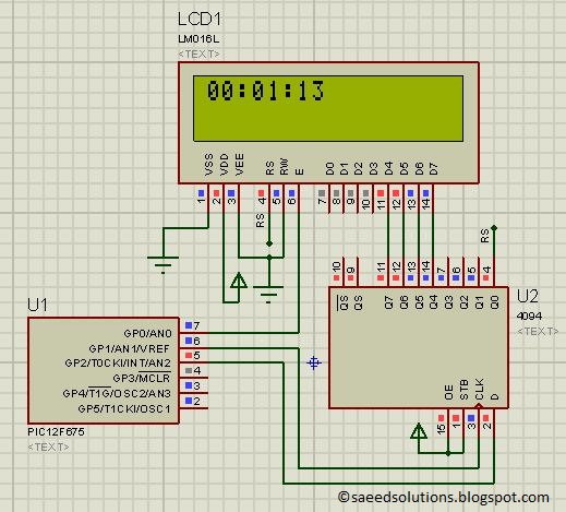
The result of simulating the code in Proteus is shown below.
The above figure was taken after 1 minute and 13 seconds of code simulation in Proteus. In the code, timer0 is used as the base for digital clock generation. Timer0 is used here to generate 1msec interrupts. After every 1msec a global variable named msCounter increments. When msCounter reaches a value of 1000 then another global variable named secCounter increments and this process repeats itself. Similarly, when secCounter reaches 60, then minCounter increments. And when minCounter reaches 60 then hrCounter increments. This process continues until hrCounter reaches 24 then all of these variables reset their values. LCD is updated with the new values of hrCounter, minCounter and secCounter after every second.
Code
The main function code is shown below.
Downloads
Digital clock display code using PIC12F675 was compiled in MPLAB v8.85 with HI-TECH C v9.83 compiler and simulation was made in Proteus v7.10. To download code and Proteus simulation click here.
For more detail: PIC12F675 based digital clock using LCD display (Code + Proteus simulation)
- How is the time base generated?
Timer0 is configured to generate 1msec interrupts. - What happens when msCounter reaches 1000?
The secCounter increments by one. - When does the minCounter increment?
The minCounter increments when secCounter reaches 60. - How often is the LCD updated?
The LCD is updated with new values after every second. - What happens when hrCounter reaches 24?
All counter variables reset their values. - Which programming language was used?
The code was written in C language. - Which compiler was used for compilation?
HI-TECH C v9.83 compiler was used. - Can I view the simulation result?
Yes, simulation results are shown after 1 minute and 13 seconds of running.