
Summary of PIC MICROCONTROLLER PROJECTS AND LCD CIRCUITS
This article presents a collection of microcontroller projects primarily using PIC and Atmega chips. Key applications include a 0-99 minute relay timer, a digital barometer, a low-power temperature recorder, rotary encoder interfaces, USB I/O boards, wireless temperature sensors, and various LCD display controllers. The projects highlight diverse functionalities like data logging, real-time monitoring, and PC communication, utilizing components such as thermistors, pressure sensors, relays, and graphical or alphanumeric displays to create versatile embedded systems for educational and industrial use.
Parts used in the Relay Timer Project:
- PIC16F628A microcontroller
- 4.0 MHz external crystal
- HD44780 based 16×2 character LCD
- Tact switch inputs (RB0, RB1, RB2)
- Relay controlled by RA3 pin
Parts used in the Digital Barometer Project:
- Atmega8 microcontroller
- Graphical LCD display
- SCP barometer pressure sensor
Parts used in the Temperature Recorder Project:
- Microchip PIC microcontroller
- Serial EEPROM (32kBytes)
- Thermistor
- Analogue circuit
Parts used in the PIC Controlled Relay Driver Project:
- PIC16F84A microcontroller
- Four relays
- 1:1 line filter transformer
Parts used in the Rotary Encoder Project:
- 24 position rotary encoder
- 16 LEDs arranged in a circle
- A6276 16 LED serial driver IC
- PIC182550 microcontroller
Parts used in the PICkit2 Programmer Project:
- Transistor
- PIC16F2550 microcontroller
- Resistors
- EEPROM
Parts used in the USB Input/Output Board Project:
- PIC18F2455 or PIC18F2550 microcontroller
Parts used in the Wireless Temperature Sensor Project:
- PIC12F675 microcontroller (SO8 package)
- LP2950 linear power supply
- DS18B20 1-Wire temperature sensor
- Sure TTL Bluetooth Module
Parts used in the USB LCD Interface Project:
- PIC18F2550 microcontroller
- Alphanumeric LCD display (e.g., 4x20)
Parts used in the Pinguino Development Board Project:
- PIC18F4550 microcontroller
- 40 pin PIC development board
Here is 0 to 99 minutes relay timer using PIC16F628 microcontroller and 16 character LCD display. The microcontroller is PIC16F628A running at 4.0 MHz clock using an external crystal. An HD44780 based 16×2 character LCD is the main display unit of the project where you can watch and set the timer duration using tact switch inputs. There are three tact switches connected to RB0 (Start/Stop), RB1 (Unit), and RB2 (Ten) pins. You can select the timer interval from 0-99 min using Unit and Ten minute switches. The Start/Stop switch is for toggling the timer ON and OFF. When the timer gets ON, a logic high signal appears on the RA3 pin, which can be used to switch on a Relay. The circuit diagram of this project is described below. 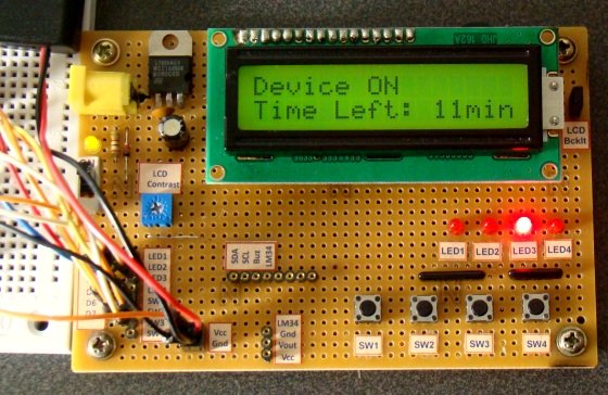
Here’s a digital barometer that uses Atmega8 microcontroller and graphical LCD display. This project uses SCP barometer pressure sensor graphical LCD display connected to Atmega8 microcontroller. Graphical LCD displays latest 128 readings while one reading occur once in 20 minutes. You can see information of about two last days. Provided C source code can be customized to your liking.
This project uses a Microchip PIC microcontroller, a serial EEPROM and a thermistor to create a temperature recorder. The temperature is measured and stored at user programmable intervals; this can be from 1 second to 256 seconds. The time interval is set by programming it and the start time into the EEPROM. Most of the time the PIC will be asleep and the EEPROM IC is inactive. This gives a very low current consumption of approximately 50 uA or about 1 mAh per day. The EEPROM used is 32kBytes which can store up to 32,000 measurements. This could be one measurement every 30 seconds for 11 days for example. The combination of thermistor and analogue circuit gives a range of between about -40 °C and +100 °C although the linear range is between about -10 °C and +40 °C.
A bootloader enables download of hex-files directly into the flash-memory of a PIC or other microcontroller. The bootloader receives the user program via the PIC’s UART and writes it directly to the program memory (self programming). This feature greatly speeds up the development process, because the chip remains in the target circuit and need not be moved between the target circuit and the programmer. When no bootloader is installed, all memory in the PIC can be utilized for user programs. That is 4 K for the 16F873 (0x000 to 0xFFF). Installing a bootloader means, that some part of the memory is occupied by the bootloader. The user can download his program into the remaining memory space. The bootloader in figure 1 occupy 256 words (0xF00 to 0xFFF), that is 6 % of the memory in a 16F873. The disadvantage of loosing 6 % memory is little compared to the advantage of fast program download and more friendly development routines.
We love to read emails from our visitors, Please let us know by clicking here if you find any kind of bug/error in our site. We will fix it as soon as possible. PIC Controlled Relay Driver This circuit is a relay driver that is based on a PIC16F84A microcontroller. The board includes four relays so this lets us to control four distinct electrical devices. The controlled device may be a heater, a lamp, a computer or a motor. To use this board in the industrial area, the supply part is designed more attentively. To minimize the effects of the ac line noises, a 1:1 line filter transformer is used.
Rotary encoders are very versatile input devices for microcontroller projects. They are like potentiometers expect of digital nature and unlike analogue potentiometers they never wear down. Rotary encoders not only provide 360 degrees of rotational freedom they also allow digital positioning information to be gained without the use of analogue to digital converters (ADCs). When using rotational encoders in projects it’s possible to use the same encoder to represent a number of different input types, however this requires some form of feedback display to let the user know what information he is inputting and the ‘position’ of the encoder. The project is based around a 24 position rotary encoder, 16 LEDs arranged in a circle around the encoder, an A6276 16 LED serial driver IC and the PIC182550 microcontroller. A rotary encoder has 3 pins usually called A, B and C. The C pin (which is normally the centre pin) should be grounded and both A and B should be connected to the microcontroller with individual pull-up resistors on each input. In this project I used RB4 and RB5 on the PIC to connect the encoder; this has 2 advantages, firstly you can use the PORTB internal weak pull-up (which means you do not need external resistors) and also the PIC provides an ‘interrupt-on-change’ which can be used to monitor the encoder.
For a long time I needed a good programmer pussy, even if it is programming, so from time to time the application gets where it is used. So I decided to build the programmer. I chose between a couple of projects from different authors, but eventually won PICkit2. Microchip released the schema directly in the user manual for the programmer. On the Internet there are multiple versions of the programmer, it’s usually cropped version of the log analyzer features, UART terminal, etc., 12V inverter is a modified version of it and control the MOSFETs, unlike bipolar transistors used in the original design. And it also showed that becomes due to the switching inductance feta leave. Finally, I chose to use the original scheme, although it is quite complicated and the parts used in our country can not normally buy, but my problems with finding parts easily solved. I bought a transistor, the 16F2550 PIC and a few other things, resistors and fry the rest I bought from “us”. The price is pretty high, unfortunately, moving it around and 600CZK, the main prize and two processor makes the EEPROM. Below we describe the involvement and put into operation.
USB Input / Output Board is a spectacular little development board / parallel port replacement featuring PIC18F2455 / PIC18F2550 microcontroller. USB IO Board is compatibile with Windows / Mac OSX / Linux computers. When attached to Windows IO board will show up as RS232 COM port. You can control 16 individual microcontroller I/O pins by sending simple serial commands. USB Input / Output Board is self-powered by USB port and can provide up to 500mA for electronic projects.
One morning I woke up and wanted to know what the temperature outside was, and instead of running over to Home Depot and picking up a $2.00 glass thermometer, I decided to build my own wireless temperature sensor. At the heart of the board is a PIC12F675 microcontroller in an SO8 package. The right-hand side of the board houses the linear power supply (LP2950), bottom-center is the DS18B20 1-Wire temperature sensor, and out in left-field you can see the Sure TTL Bluetooth Module.
The new PIC18F2550 Project Board was designed as the development platform for student projects. The board platform is suitable for developing the microcontroller based instrumentation. Students may build the signal conditioning board, plugs it to PIC project board, develops the code and programs it with loader cable easily.
If you like PC modding this is cool project for you.this is an USB interface for alphanumeric LCD display like 4×20 which can be controlled with LCDSmartie program.USB interface is implemented by using PIC18F2550 microcontroller. Using USB LCD module you can view many types of information taken from PC like temperatures, time/date, MP3 song titles, view emails, RSS feeds all that LCDSmartie or other program supports. 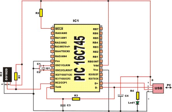
Pinguino is an Arduino-like board based on a PIC Microcontroller. The goal of this project is to build an integrated IDE easy to use on LINUX, WINDOWS and MAC OS X. This is a simple 40 pin PIC development board as described in RadCom for November 2009. It is designed for a PIC18F4550, but it will work with other 40 pin PICs like the PIC16F877A. It has no bells & whistles attached. No buttons, LED, LCD ICSP etc. All of the PIC pins are easily accessible so that you can add any features you need. This board has been tested with the Vasco PUF and the Pinguino USB bootloaders.
For more detail: PIC MICROCONTROLLER PROJECTS AND LCD CIRCUITS
- How does the relay timer project toggle the timer ON and OFF?
The Start/Stop switch connected to the RB0 pin is used to toggle the timer ON and OFF. - What is the maximum duration the 0 to 99 minutes relay timer can measure?
The timer allows selecting an interval from 0 to 99 minutes using Unit and Ten minute switches. - Can the digital barometer display readings from previous days?
Yes, the graphical LCD displays the latest 128 readings, allowing information about two last days to be seen. - How much memory does the bootloader occupy in a 16F873 microcontroller?
The bootloader occupies 256 words, which is 6% of the memory in a 16F873. - What type of transformer is used in the PIC Controlled Relay Driver to minimize AC line noise?
A 1:1 line filter transformer is used to minimize the effects of AC line noises. - Why are rotary encoders preferred over analogue potentiometers in some projects?
Rotary encoders never wear down unlike analogue potentiometers and provide digital positioning information without needing ADCs. - Does the USB Input/Output Board require an external power source?
No, the board is self-powered by the USB port and can provide up to 500mA for electronic projects. - What module is used for wireless transmission in the custom temperature sensor?
A Sure TTL Bluetooth Module is used for wireless transmission in the temperature sensor project. - Which program supports viewing MP3 song titles on the USB LCD interface?
The LCDSmartie program supports viewing information like MP3 song titles on the USB LCD interface. - Is the Pinguino board compatible with operating systems other than Windows?
Yes, the goal of the Pinguino project is to build an IDE easy to use on LINUX, WINDOWS, and MAC OS X.
