Summary of DIY dynamic electronic load
This article details the design of a DIY dynamic electronic load capable of stepping current up to 5A continuous and 330Hz pulsed to test power supply transient responses. The project prioritizes simple, readily available components and robust analog circuitry performance. Built on a double-sided PCB using an LPKF milling machine, the prototype handles approximately 40W of dissipation without built-in protection circuits. Circuit modeling was performed using LTspice.
Parts used in the Dynamic Electronic Load:
- Readily available components
- Analog circuitry
- LTspice software for modeling
- Double-sided board
- LPKF milling machine
Hi group,
A while a go I shared my design for a small electronic load that was limited to dc operation only. I am in the process of design and construction of a dynamic load. The dynamic load steps the load current so that the transient response of the power supply being tested can be observed.
I have decided to keep the design simple using readily available components. I have also focused on performance of the analog circuitry.
Features:
0-5A maximum continuous current
0-5A pulsed current at 330Hz
Maximum dissipation around 40W (There is no protection circuits in the design)
LTspice was used for circuit modelling. I have attached the LTspice model in a zip file attached to this post.
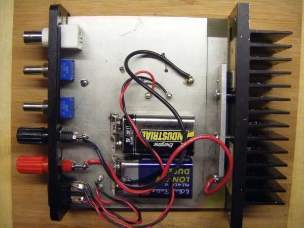
The prototype was constructed on a double-sided board made on an LPKF milling machine.
For more detail: DIY dynamic electronic load
- What is the primary function of this dynamic load?
It steps the load current so that the transient response of the power supply being tested can be observed. - How much maximum continuous current does it support?
The device supports a maximum continuous current of 0-5A. - Can it handle pulsed currents?
Yes, it handles 0-5A pulsed current at 330Hz. - What is the maximum power dissipation of the prototype?
The maximum dissipation is around 40W. - Does the design include protection circuits?
No, there are no protection circuits in the design. - Which software was used for circuit modeling?
LTspice was used for circuit modelling. - How was the prototype constructed?
The prototype was constructed on a double-sided board made on an LPKF milling machine. - Is the design considered complex?
The author decided to keep the design simple using readily available components.