Summary of PIC Game System
This article details a PIC16F84-based video game system originally made in 1998 and updated in 2007 to support the PIC16F628A. The system generates video (PAL/NTSC) and audio via software with a 12 MHz PIC microcontroller, supports two standard C64/Amiga/Atari joysticks, and uses a simple hardware design including a 7805 voltage regulator and a two-bit DAC for video. It features basic square wave audio and protective resistor networks for joystick input lines. Programming connectors and an optional built-in joystick PCB layout are included. Available kits, PCBs, and preprogrammed chips can be purchased.
Parts used in the PIC16F84-based Video Game System:
- PIC16F84 or PIC16F628A microcontroller
- 12 MHz crystal oscillator
- 7805 voltage regulator
- Diode (for input protection)
- Capacitor (input smoothing)
- Two C64/Amiga/Atari joysticks (or built-in joypads on PCB)
- Resistor network: 100k pullups for inputs
- Series resistors: 1k for IO pin protection
- Two resistors for two-bit DAC video output
- 1k potentiometer (audio volume control)
- 2.7k resistor (audio voltage divider)
- Programming connectors (10-pin and 6-pin IDC)
- Standard push buttons (for built-in joystick PCB version)
This page describes a PIC16F84-based video game system I made and first published back in the beginning of 1998. Now, beginning of 2007, nine years later I’ve updated the layout of the PCB and also updated the source code to also be able to run on a PIC16F628A as Microchip is phasing out the 16F84 and it will soon not be able to be bought. The final new “feature” is that you now also can buy PCBs, preprogrammed chips and of course complete kits from me in my web shop.
I have designed the hardware of the PIC video game system to be able to run several different kinds of games. It has two standard C64/Amiga/Atari joysticks and video and audio output. The processor is a PIC16F84 running at 12MHz and generates both video (PAL and NTSC) and audio in software. The description of the hardware is placed on this separate page as it is the same for both of my PIC-based video games. So far I’ve only made two games, Pong and Tetris, but some day there might be more games for the system. (Most unlikely that I write more games though as I probably will write more games for the color SX-system instead).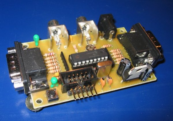
The hardware design
The hardware design is quite simple. The power supply section is just a standard 7805 regulator to get the voltage to 5v, and it has a diode and a cap at the input so it can be fed with both AC and DC (input voltage should be 8..15v something).
Two C64/Amiga/Atari joysticks are used as input for the games. Each joystick has four direction switches (up,down,left,right) and one fire switch. These five switches just short the IO line to ground when moving the joystick around and pressing fire button. This kind of joystick could be connected directly to the IO pins, but it need some resistor nets for protection, I’ll get back to why soon.
The video is generated by a two bit DA, using only two resistors and the input impedance of the TV. To be able to get a higher resolution, the software uses PORTB as a shift register. (I got the idea for this from Eric Smith) So that is why the two bits are on different IO-registers. One problem with using one IO register as a shift regster is that one looses a lot of IO-pins by doing this, but I solved this by using 100k pullupps and 1k seral resistors for protection on the remaining IO-pins so they could be used as input pins for the joystick. When the pin is set as an input the voltage in will be 5v thanks to the pullup when the joystick switch is open, and 5v*1k/100k=0.05v when the switch is closed. When the pin is set as an output, the 1k resistor will protect the IO-pin from too high currents during shifting operation when the joystick switch is closed.
The audio has one bit only and is thereby limited to one channel square wave audio. The 1k potensiometer and the 2k7 resistor forms a voltage divider making an adjustable voltage limit of zero to 5*1/(1+2,7)=1,35v assuming the load resistance is much larger than 1k. The audio is only able to drive a line-in input on a TV, amplifier or similar, but not earphones or similar device with low impedance. As the output is only a square wave the audio sounds terrible but the system has sound this way even if it sounds bad.
Programming connectors has nothing to do with the operation of the gaming itself so they are left out in the schematic above, however they are needed if the system shall be able to change game without changing the PIC so my PCB-layout has two in circuit programming connectors, one 10pin connector, supporting my own upcomming multiprogrammer, and one 6p supporting microchips programmers such as the pickit2. (People that built the system using my old layout should note that I had only a connector for Jens Madsens programmer in the old design, so the programming connector has changed for the new layout)
Note that when programming a PIC16F628A in system you will have problems if your PIC has low voltage programming enabled. This due to that RB4 is pulled up to VDD forcing the PIC into low voltage programming mode which means problems when trying to programming it in high voltage mode. The simple solution to the problem is simply to push the left joystick to the right (or push right on the left joypaddle if using layout with built-in joypad) to be able to program it in high voltage programming mode.
To make it easier to build the game system, I’ve made a building instructions page for this system on how to build it, assuming you are using my PCB layout and the same kind of components. (There is a separate building instruction page for the joypad version of the layout.)
Note that most of the component values in the schematic are not very critical, they may vary at least plusminus ten percent without affecting the system greatly, but with one exception, the chrystal must be exactlyt 12MHz otherwise the video timing gets messed up and you will not get a stable picture.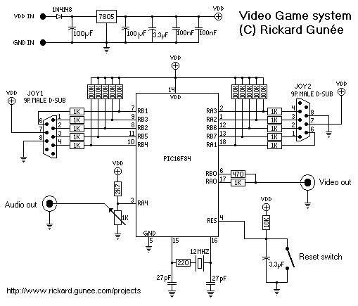
Joysticks.
The joysticks used for this game is old C64/Amiga/Atari joysticks. I’m using two old Tac2 joysticks. there are probably a lot of these old joysticks out there, but if you don’t have access to one, then you could build one using the schematic in the picture below or build the version with built-in joystick described in the further down on this page.
Schematic for a C64 compatible joystick
PCB with built-in joysticks
As it has been requested by several people, now I’ve created a special version of the PCB with two joypads on the PCB, as seen in the picture here to the right. Both the layout woth the built-in joystick and the standard one (using a C64/Amiga/Atari joystick) are included in the zip-file. The layout supports two common footprints and thus can be used for several types of buttons. There is a separate building instruction page for the joypad version of the layout.
Pictures of three types of buttons supported by the PCB. (Click to enlarge)
For more detail: PIC Game System