


Summary of PIC based WWVB clock
This article details a DIY WWVB atomic clock project using a PIC 16F628 microcontroller to decode time signals from Fort Collins, CO. The design features automatic synchronization, daylight savings detection, and a 12-hour 6-digit LED display. It operates best at night and maintains local time during signal loss.Parts used in the PIC based WWVB clock:
- PIC 16F628 microcontroller
- C-MAX model CMMR-6 WWVB receiver with loopstick antenna
- 1-inch red-orange LED seven-segment displays (six units)
- Seven-segment decoder/drivers
- 4-bit data bus components
- Free schematic editor software
- Free C compiler for PIC
- Free PCB layout software
- Free PIC programmer
Introduction
There are many DIY versions of WWVB clock designs available on the web. Commercial "atomic" clocks are inexpensive and widely available, but I wanted to try my hand at designing one to gain insight into WWVB reception and to learn a little about programming a PIC microcontroller. My version is not the simplest available, but it works well and I think it offers a few unique features.
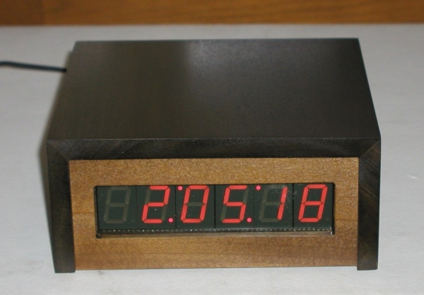 WWVB Clock Features
-
-
Receives time broadcast from WWVB, Fort Collins, CO
-
-
Auto synchronizes internal time with WWVB time
-
Maintains local time when WWVB signal is lost
-
This version is for Pacific Standard Time, and auto detects/corrects for Daylignt Savings Time
-
6-digit display of hours, minutes, seconds using 1" seven-segment LED displays
-
WWVB sync indicator
-
Time display is in 12-hour format
-
PIC 16F628 microcontroller
-
Software written in C
-
All tools (schematic editor, C compiler, PCB layout software, PIC programmer are free and available for download on the web.
A complete description and specification for the WWVB broadcasts is available (free), document # 432, at tf.nist.gov/general/pdf/1383.pdf The WWVB signal is broadcast as a 60 kHz carrier that is AM modulated with a time code frame that is updated once per minute. The data rate is one bit per second. Along with time code information, the data frame also contains synchronization bits, calendar data, UT1 correction, leap year, and leap second data. The clock design presented here only decodes the time data and daylight savings correction data. The software could easily be modified to include decoding of the other information bits, if desired. The the low frequency WWVB signal strength is weak and reception can be problematic. Signal acquisition time is variable, depending on location and atmospheric conditions. Reception is usually best at night between 8pm - 4am. To use the clock, just apply power and wait for reception of the WWVB signal. When the clock receives a complete error-free frame of data, it will automatically reset the display to show the correct time. After the initial time correction, the clock will maintain time even if WWVB reception is lost.
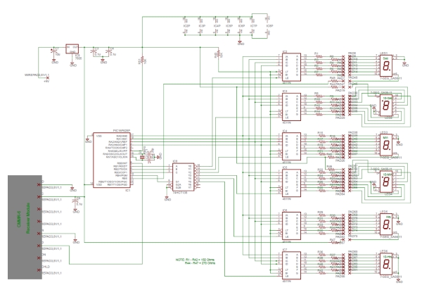 As shown in the schematic (pdf format), the heart of the clock is a PIC 16F628 microcontroller running at 4 MHz. Decoded time data is sequentially output from the microcontroller (RA0 - RA3) to the 7-segment decoder/drivers on a 4-bit data bus. The data is output sequentially as seconds, 10s of seconds, minutes, 10s of minutes, hours, and 10s of hours. The microcontroller outputs (RB1, RB2, RB3) route a 10 uSec stroble pulse from RB4 out to each of the 7-segment decoder/drivers at the proper time to latch the data bus values. Seconds and 10s of seconds display values are updated once per second. Minutes, 10s of minutes, hours, and 10s of hours are updated once per minute. The display consists of 1" red-orange LED 7-segment displays. The decimal points on the displays are used to form colons to separate the seconds, minutes, and hours. The 10s of seconds and 10s of minutes displays are mounted upside down to form the upper colon dots. The WWVB receiver is a C-MAX model CMMR-6 and is available from Digi-Key (www.digikey.com) as part # 561-1014-ND complete with loopstick antenna. Data output from the receiver is sampled by the microcontroller on RB0.
For more detail: PIC based WWVB clock
-
How does the clock maintain time when the signal is lost?
The clock maintains local time even if WWVB reception is lost after the initial time correction. -
What is the best time of day to receive the WWVB signal?
Reception is usually best at night between 8pm and 4am due to weak signal strength. -
Does the clock automatically detect Daylight Savings Time?
Yes, this version auto detects and corrects for Daylight Savings Time for Pacific Standard Time. -
What type of microcontroller is used as the heart of the clock?
The clock uses a PIC 16F628 microcontroller running at 4 MHz. -
How often are the seconds displayed updated?
Seconds and 10s of seconds display values are updated once per second. -
Can the software be modified to decode other data bits?
Yes, the software could easily be modified to include decoding of calendar, leap year, or leap second data. -
What part number identifies the recommended WWVB receiver?
The C-MAX model CMMR-6 receiver is available from Digi-Key as part # 561-1014-ND.
Related projects
DHT11 Low Cost Humidity Sensor using PIC16F628A with Proteus Simulation
IntroductionThis microcontroller project demonstrates how to interface a low-cost DHT11 temperature and humidity sensor with a PIC16F628A using a Proteus simulation environment.The...
LCD & Display Projects · PIC16F628AFrequency Counter by PIC16F628
In this project we are building a basic and low cost frequency counter circuit . It can measure from 16Hz to 100Hz...
Games, Toys & Calculators · PIC16F628ATIC TAC TOE game using PIC16F628
This project is not to introduce Tic Tac Toe. Everyone knows this game. It's to introduce two features. Bi-coloured LEDs, microcontrollers and...
Clocks & TimersAdaptive Alarm Clock: Build a Smart, User-Centric wake-Up system
Project Overview The goal of this ambitious undergraduate project was to develop a novel alarm clock capable of analyzing a person's unique...
Clocks & TimersDesigning Your Ideal Alarm Clock: An Introduction to PIC18
Within this laboratory session, you'll employ the C language to create an alarm clock, delving into the implementation of "C" programs on...
Clocks & TimersBuilding your Dream Alarm Clock Using the PIC18
Objective: In this laboratory session, your objective is to create an alarm clock using the C programming language. You will gain proficiency...

Ibrar Ayyub
I am an experienced technical writer holding a Master's degree in computer science from BZU Multan, Pakistan University. With a background spanning various industries, particularly in home automation and engineering, I have honed my skills in crafting clear and concise content. Proficient in leveraging infographics and diagrams, I strive to simplify complex concepts for readers. My strength lies in thorough...