Summary of PIC BALL MACHINE
### Summary The article details the design and implementation of "PICBall," a PIC32-powered pinball machine featuring solenoid-actuated flippers, 3D-printed obstacles with limit switches, copper tape track sensors, and a 7-segment display. The team faced significant challenges integrating mechanical and electrical components, particularly managing electromagnetic interference (EMI) from high-current solenoids which caused false interrupt triggers. Solutions included hardware modifications like capacitors and foil shielding, alongside software debouncing routines to ensure reliable gameplay.
Parts used in the PICBall Machine:
- PIC32 microcontroller
- 12V 8A solenoids
- 2A solenoids (tested but rejected)
- AutoDesk Inventor CAD software
- 3D printer
- Plywood playing field
- Limit switches
- Copper tape
- 4-digit 7-segment display
- Adafruit 7-segment clock display
- BCD-to-7-segment CMOS decoder
- LED strip
- 2SK4017 power MOSFETs
- 2N3904 NPN transistors
- Solenoid power supply (15V 8A tuned to 12V)
- Bench adjustable power supply
- 9V battery
- Launch spring
- Wooden dowel
- Teflon strip
- Chopsticks
- Flyback diodes
- Capacitors (0.01uF and 0.1uF)
- Aluminum foil
Introduction
Our ECE 4760 final project is PICBall: a PIC32-powered, old-school pinball machine!
When trying to come up with a project that would encompass multiple parts of the class, we figured a more physical project (as opposed to virtual project) would be the most fitting. At the same time, per the recommendations given on the final project page on the ECE 4760 website, we wanted a project that we really liked, would be fun to work on, and was both mechanically and codewise complex. What we eventually came up with was a spin on the classic mechanical pinball machine, which we thought would be an interesting way to integrate software components that we had learned in class into a highly interactive physical product.
High Level Design
We quickly came to learn that there was a staggering number of design obstacles that we had to overcome in order to make our pinball machine successfully and satisfyingly playable. Although it may seem like many of the components, such as the flippers, playing surface, and launching mechanism are purely mechanical, there was a lot of room for electrical integration that we were striving for. Indeed, integration was the most difficult aspect of our project: designing the physical components to be mechanically sound while leaving room for adding wiring and other electrical components would prove to be the most time-consuming part of the project, especially when we also had to consider aesthetics. In this section, we will describe the overall design and components involved in our project, while in the next section we will go into detail about the challenges we faced during implementation.
Flippers
The first aspect of the pinball machine that we considered were the flippers, since they’re literally the driving force behind pinball machines. After doing some research online and watching videos on YouTube about constructing a pinball machine, we chose solenoids as the actuation mechanism for the paddles since they would give enough power to launch the ball across the playing field. We chose 12V, 8A solenoids which we bought from Amazon since when we tested with 2A solenoids, the impulse was not nearly strong enough to launch the ball any significant distance. We then used CAD (AutoDesk Inventor) to design and visualize the physical parts we’d need for the game, including the paddles and obstacles on the playing field, which we felt would be best suited for 3D-printing. After thorough prototyping, the following design worked the best for the flippers:
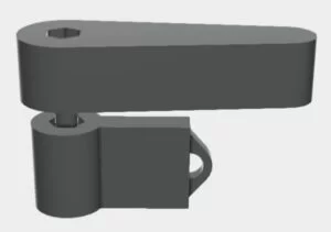
As seen in the above pictures, the flipper actuation mechanism is composed of two pieces: the flippers and a lower actuation piece. Holes for a screw was designed into both pieces such that these two pieces sandwich the plywood playing field and move as a single unit. In order to avoid having the flippers rotate about the screw every time it was actuated, we allowed enough space within both the flipper and the back piece such that lock nuts could sit inside of them to secure both pieces in place relative to each other and the screw. Lastly, the long end of the back piece rests on the solenoid in its resting state such that when the solenoid is actuated the back piece turns, moving the flipper accordingly. The back piece also has a hook on it, which we used to tie a rubber-band around and connect to the solenoid loosely; when the flipper is actuated, the back piece is pulled back due to the rubber band and the flipper can quickly return to its natural position. The solenoids were then connected up to buttons on the side of the machine.
Obstacles
In addition to the flippers, we also used CAD to design the obstacles on the playing field: two triangular bumpers and a boomerang-shaped bumper. These also went through several revisions since they were the most important element for scoring, and we had to make sure that the ball would interact with them properly. In fact, the next thing we had to consider was how to properly keep score. Since points in pinball are accrued through contacting obstacles, we thought that given the power of the flipper solenoids, limit switches would work well for detecting impacts against any raised obstacles on the playing field. We also decided that rather than continuously polling for input, which would be wasted time on the processor, we would have limit switch inputs trigger interrupts, which should be more consistent for detecting impacts (Schematic in Appendix B).
For the triangle obstacles, we chose to put two limit switches for the long side and one for each shorter side. Since the switches are normally open, we tied all four normally open terminals together and all four common terminals together. A hole was drilled in the board such that the bunch of switches could be threaded through it. The obstacle was then placed over the hole and the switches were placed along the perimeter of the obstacle as such:
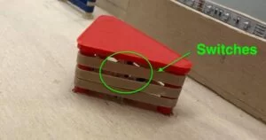
The rubber bands were used to both protect the switch and also provide the bounce-back effect of typical pinball obstacles. The common leads were grounded and the NO (normally open) leads were tied to a free pin on the big board. This was also done for the boomerang, where we used an additional 2 switches since the obstacle was larger. An interrupt for an obstacle would be triggered whenever one of the switches was depressed, which would increment the score by 50.
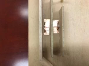
Again drawing inspiration from classic pinball machines, we decided to add two tracks on the left side of the playing field. These would be relatively harder to reach than simply hitting the bumper obstacles, so the amount of points for going down these tracks was worth double the amount for bumper obstacles. At the suggestion of Professor Land, to detect when balls rolled down the tracks, we tried using two pieces of copper tape are placed extremely close together such that when the metal ball rolls down the track and over the tapes, a connection is made, triggering an interrupt and incrementing the score by 100. The triggering was rather consistent, and was a fantastic addition to the game but the mechanism itself would prove to be slightly problematic; this will be discussed in the “Results” section.
Other Designs
The score was displayed on a small 4 digit 7-segment display, which we placed at the top right of the machine. Sound was also played whenever an obstacle was hit or the ball ran over the tracks. We modelled the sounds after classic pinball sounds like the cashing of a cash register and the tune of a slide whistle. A start lever was placed on the top right of the machine and an LED strip was added to change color according to the state of the game and the current score.
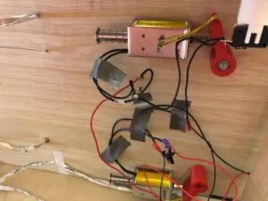
There were a couple of design decisions that had to be made along the way, namely how to launch the ball. After much back and forth, we decided that a launcher would stay most true to the pinball game and would be an interesting challenge to create. After luckily finding a good spring in lab, we designed the launcher by threading a wooden dowel through the spring with a square piece on the end of it. The other end of the dowel is threaded through a wooden block attached to the playing field, and the spring is glued on both ends to the wooden pieces. The launch mechanism can be seen as follows:
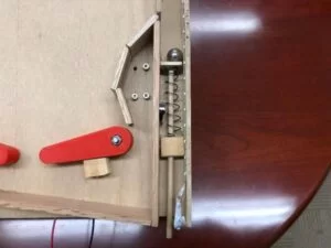
Subsequently, we decided that having a rounded top would provide better game play and make the ball launch a lot smoother as the ball could ride out the curved top. We found a piece of teflon in lab, cut up chopsticks, placed the cut pieces around a semicircle, and then glued the teflon to it, making up the back rim. The linear guides were also relatively freehanded, although we had originally CADed a design for them.
It is also important to note that we grossly overestimated the steepness of the incline for the game; we propped up the front of the machine with thick books to decrease the slope such that game play would be more fair and the copper tape had time to actuate.
With regard to power supplies, a 15V 8A power supply tuned down to roughly 12V powered the solenoids. One of the lab bench adjustable power supplies powered the LED strip, which was a 12V strip that drew up to 0.5 amps. We powered the PIC itself using a 9V battery rather than the 5V power supply in an attempt to reduce the effects of electromagnetic interference from the solenoid circuit (more detail in the results section).
Hardware and Software Design
Hardware Design
There were many components in our project that underwent several iterations before producing results that we were satisfied with. The biggest example of this was the flippers. The original flipper design did not have room for nuts to be secured within either the flipper or the actuator piece. This made attaching the pieces to the screw very difficult, since there was no way to keep them from rotating about the screw during an impact. The next iteration added nut-shaped holes on one side that would secure the pieces much better; however, we found that the impulse from the solenoid was still so great that it would turn the piece about the screw, and so we needed to secure both pieces tightly on both sides. We redesigned the paddles a third time to account for this; this third redesign was much more successful, but after some period of continuous gameplay they would still get loose. Unfortunately we did not have time to go through another design iteration to make them work exactly as we had wanted.
Likewise, the bumpers also underwent a key redesign. The first time we 3D-printed the bumpers, they outwardly looked fine but as soon as we put the rubber bands around them, the legs snapped off from the base. The redesign for the small bumpers involved making the triangular piece thicker for more strength, and also making the legs thicker in diameter to have more contact with the top triangular piece to more easily withstand the rubber band tension.
We knew from the start that we wanted tracks that would score points when the ball rolled through them, but once we had attached the plywood for the tracks we ran into the issue of how the PIC would be able to know when there was a moving ball within the track. We first attempted different ways of mounting the limit switches we had, such as gluing them on in different configurations, and also tested drilling openings in the playing field surface to mount the sensors from below. However, none of these attempts gave good results; the switch would either block the ball, or the ball would not trigger the switch consistently. Thus when we consulted Professor Land about this problem, he offered to us the copper tape solution, where the ball would make a connection across two pads if they were close enough together when the ball rolled over them. This solution was much more consistent, and was also ideal because it did not affect the ball’s movement as it rolled down the track.
For the back rim, we experimented with several designs as well. At first we considered many small wood pieces put together such that they would make a rough semi-circle. This didn’t allow the ball to roll smoothly across the top, however, which was the main goal of the rim. Our second idea was to use cut chopstick pieces as pegs to form the semicircle, and then test out various materials in between the pegs to see which would facilitate smoother movement. We found that Professor Land happened to have a teflon strip that was just about the right length, and when we tested the strip it yielded the best results, with the ball rolling uninterrupted across the entire semicircle just as one would expect from a real, polished pinball machine.
Electrical Design
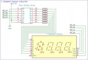
For the electrical design, there are four important circuitry systems to note: the 7-segment display, the switches triggering interrupts, the LED strip, and the solenoids (all four system schematics in Appendix B). For the 7-segment display, we used the Adafruit 7-segment clock display with a BCD-to-7-segment CMOS decoder for the scoreboard. The purpose of the decoder was to allow a BCD (Binary Coded Decimal) value to be decoded into the proper 7-segment output; for example, we could feed in 0011 from four PIC output pins into the DA, DB, DC, and DD ports on the decoder, and the decoder would turn on the proper segments in the display to show a “3”. Four other PIC output pins are used to drive pins CA1, CA2, CA3, and CA4 on the display itself. Each of those pins correspond to a digit; if the pin is driven high, the digit is turned on. By rapidly cycling through each digit and different BCD values, we can display four different numbers on each of the digits on the display, which was necessary for scorekeeping.
All of the switches that triggered interrupts were connected to one of three input ports on the PIC. The “Game Start” switch was connected to INT0 on port B7, and triggering it would reset the score and toggle between the “idle” and “game start” modes. We used two different segments of copper tape, but since they incremented the score by the same amount (100 points), we connected them to the same input A1, for INT3. Thus if the ball rolled down either track, the interrupt would be triggered, incrementing the score and playing the slide whistle sound. For the bumpers, it was the similar idea in that they also incremented the score by the same amount, and we wanted them to play the same “ka-ching!’ sound so we tied all of the bumper switches to the same interrupt, INT4 on pin B3.
For the LED strip, we used 2SK4017 power MOSFETs to turn a specific color (Red, Green, or Blue) on, off, or some value in between using PWM. We originally tried hooking up the PIC PWM output pins directly to the FET, but we found that the output voltage was lower than the switch turn-on voltage. To solve this issue, we added intermediate 2N3904 NPN transistors which would be turned on/off by the PIC PWM output, and could give the required input voltage for the 2SK4017’s. This gave us full control of each color output on the LED strip, allowing us to program several cool patterns.
Lastly, for the solenoids, at first we just had the flyback diode to help prevent the sudden voltage spike typically seen across inductive loads (in this case, the 12V 8A solenoid is a massive inductive load) when the supply current rapidly changes when the paddles are triggered/released). However, when we ran into the issue of the significant electromagnetic interference from the solenoid, we added capacitors across both of the solenoids, and also between 12V and GND in an attempt to add decoupling to the system to reduce noise. This was somewhat successful, but there were several other solutions we had to i link mplement to reduce this issue to a reasonable degree, detailed in the “Results” section.
Software Design
The first design challenge that was approached when writing the software was determining whether to poll or use interrupts for determining when the ball interacted with any of the obstacles on the playing field. While we had used the polling method to register button clicks for Lab 1, we were hesitant to use this method because in Lab 1, the thread that polled for user input ate up a large chunk of CPU time. We could not afford the same type of CPU intensive polling because we needed as much CPU time as possible to update the 7-segment display. Therefore, we decided to use three external interrupts to deal with updating the score and game start/reset. To debounce the input from the various inputs we relied on the simple methodology that we found on this online Arduino forum: https://forum.arduino.cc/index.php?topic=45000.0. The idea behind this debouncing methodology is simple: there is a static variable that records the time of the last interrupt in system time. The next time an interrupt occurs, the interrupt handler checks to see if the difference between the current system time and the last interrupt time is greater than 200ms. If it is not, then the interrupt does not do anything, and if it is, then the interrupt is processed, incrementing the score and updating the last interrupt time.
The next part of the project that we had to implement programmatically was the 7-segment display. To control the 7-segment display, we needed four pins that selected which digit to write to and four bits that set what digit to display. Because we needed a total of eight pins to run the 7-segment display, and there weren’t eight pins left on the PIC that we were not using, we decided to implement the Port Expander, which gave us the Y pins to control the display. Also, because each digit has to be turned on one at a time to set the digit, each digit would at best be on for a quarter of the total on-time of the display. However, because the port expander gets a new transmission once every microsecond, we would be able to get well over fifteen frames per second refresh rate for every digit. Thus the digits would appear normal to viewers with minimal flickering as long as we managed our CPU time properly. Each transmission to the port expander was a single byte that contained whether the pins of Port Expander Port Y were high or not. The four most significant bits of the data specified which numeral to display while the lower four bits picked which bit to turn on. So, in our scoreboard thread, we simply determined which numeral of the score to display through a set of mod and division operations, shifted the numeral four bits over, and ORed the numeral with a mask that specified which digit was being written to display the score.
Another big concern we had in relation to our 7-segment display was direct digital synthesis for sound and how much CPU time that would steal from the scoreboard thread. We could not use the DMA to handle transmissions to the DAC because the DAC and the port expander use the same SPI channel. Therefore, we cannot use framed SPI mode to control the DAC from the DMA and had to rely on timer interrupts to send transmissions through the SPI bus. Since we relied on interrupts to handle the transmission, we had two main concerns when dealing with sound and the scoreboard thread: moderating the SPI bus between the DAC and the port expander and determining the least amount of timer interrupts we could have while still having reasonable sound quality. The first issue could easily be fixed by setting up critical sections in the scoreboard thread that would disable timer interrupts before execution and enable timer interrupts after execution. To tackle the second issue, we simply relied on experimentation to find out what sample rate would work best for our system. We quickly determined that the 40 kHz sample rate from Lab 1 was simply too high as we could see the digits on the scoreboard flash on and off. But with a little bit more trial and error, we were able to settle on an 8 kHz sample rate that allowed the scoreboard to function properly while still providing moderately crisp sound quality. As for the actual sounds we used, we relied on Sam DiPietro’s MATLAB script that converts audio files to a header file with an array that contains digital samples of our sound. So, whenever a sound was queued up to be played, we would simply loop through the array of digital samples in the timer interrupt handler, one sample per invocation of the handler, to transmit to the DAC and play the sound.
The final software element that we implemented was the control for the LED strips. To turn on any of the three colors, we simply had to pull a pin connected to the LED strip low. However, such an effect is not desirable because the LEDs would be blindingly bright if they were only fully on or fully off during gameplay. Therefore, we relied on the output compare functionality of the PIC to use PWM to control the brightness of the LEDs. The output compare pins relied on Timer 2, the same timer that we used for our direct digital synthesis, so we were running the PWM at a frequency of 8 kHz. Our LED strip had two states throughout the operation of the game: a glow effect before the start of the game and another mode where each of the three LEDs would slowly start turning brighter based on the score. In the pre-game state, we relied on a triangle wave signal that would slowly increment and decrement the PWM duty cycle. Once the game started, we switched to a different mode that relies on a piecewise linear function to slowly decrement the PWM duty cycle of each LED. The first LED would turn on to full brightness at 2500 points, the next LED turns on to full brightness between 2500 and 5000 points, and the last LED turns on to fully brightness between 5000 and 7500 points.
Results
When we interfaced the Big Board to the rest of the machine and connected the solenoids up for our first test, we were pleasantly surprised that the systems appeared to be functional after being integrated. The LED strip was on, the scoreboard was displaying properly, and when we touched the switches the score would increment as intended. However, a problem arose which we noticed as soon as we triggered the flipper solenoids after integrating everything else. The most noticeable effect was that the various interrupts would trigger automatically and increment the score. Even more bizarrely, we found that we had the same issue whenever we plugged in any device into the same extension strip that was powering the PIC. To combat this issue we isolated the power for the PIC by powering the Big Board off a 9V battery, which would isolate it from the strip which was powering the external power supplies. However, this only slightly reduced some of the interference issues we were having.
Pretty quickly, we realized that the high current being drawn through the solenoids was causing electromagnetic interference (EMI), which induced current on nearby wires and thus triggered interrupts for obstacles whenever the paddles were actuated. The first thing we tried to solve this issue was to move from using internal pull-ups on our external interrupt pins and convert to external pull-ups. The reasoning behind this change was that the internal pull-ups on the pn are on the order of magnitude of a 100 kOhms and as a result there is very little difference in the current through the pin when the input is triggered as opposed to not triggered. An external 5 kOhm pull-up resistor draws significantly more current when the input is triggered, so the current induced by the EMI from the solenoids would be less likely to trigger the interrupt. While this method worked to cut down some of the interference there was still an unacceptable amount affecting game play.
Our next approach was placing 0.01 micro Farad capacitors across the solenoids to act as a low pass filter and suppress some of the high frequency noise from the solenoid from interfering with the PIC. We also placed a 0.1 micro Farad capacitor across the terminals of the solenoid power supply. We did this so that when the solenoids are not activated, the capacitor would be charged up slowly, and when the solenoids are activated, the capacitor is discharged and provides some of the 8A of current needed to power the solenoid. This way, there isn’t as much strain placed on the power supply to supply the current needed to power the solenoid and there would be a lower current spike from the power supply and lower EMI on the PIC. Unfortunately, while this solution helped the problem, we were not able to fully fix the problem.
Our last attempt implemented through hardware was to create a Faraday cage around any of the wires that were connected to the obstacles in hopes that the cage would shield the wires from any excess charge. After finding a roll of foil in the lab, we began to wrap these wires from the base of the board all the way to the PIC itself. For each pair of wires (ground and pin), we grounded the foil to the board and moved the wrapped wire as far away from the solenoids as possible. While this solution worked surprisingly well for the bumpers, the interrupt would still get triggered every so often because the copper tape is an exposed conductor and covering them in would not be possible. Thus, we resorted to using software to debounce some of the interrupts as well.
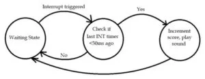
Our approach with debouncing the software was based on our assumption that the EMI from the paddles is very brief, but just long enough to trigger the interrupt once. Placing the interrupt on the oscilloscope demonstrated that our hunch was correct, for a very brief moment in time, the signal would be pulled low when the paddle is actuated. So, with this in mind, we designed a new interrupt debouncing routine where two successive interrupts would have to be encountered within 50 ms to register as a valid interrupt input. The idea is that the impulse was fast enough to trigger one interrupt, so to try to filter out misfires two successive interrupts would have to be generated, which would more likely correspond to a legitimate scoring mechanism triggering. We designed a simple FSM (shown below) in which the state after “waiting” corresponds to the first interrupt handler call and the third state corresponds to the second interrupt handler. The transition from the second state to the third state only happens if the interrupt is triggered again within 50 ms. Once the FSM reaches the third state, we go through the additional debouncing routine from before the score is updated. So, for the score to be updated twice from the same interrupt, the interrupt handler has to be called four times with a latency of at least 300 ms between the first and last interrupt call. We reached upon this value of 50 ms by manual tuning of the system and seeing what value would capture almost all the proper interrupt triggers while eliminating as many misfires as possible.
This debouncing routine worked really well for the most part and eliminated almost all of the noise. Sometimes, there are accidental triggers which increment the score and we have noticed that this could be linked to coupling effects from the ball travelling through the playing field. We have deduced from experiments where the ball is not in play and when the ball is in play that the EMI gets significantly worse when the ball is in play. Our assumption is that the conductive nature of the ball makes the interference that much more potent. In addition, the proximity of the wiring between the PIC and the solenoid circuits directly correlates to the potentness of the EMI. So, we ended up having to strategically place some of our inputs away from the PIC.
In the end, we were able to reduce the effects from the EMI to a degree where it would not significantly detract from gameplay; accidental interrupt triggers would occur much less frequently, although it was still inconsistent, making it difficult to obtain a definitive percentage of accidental triggers. Aside from this issue, all of our other systems worked just as we expected. The LED strip greatly enhanced the aesthetics of the pinball machine, which was our main purpose for including them in the first place. The limit switches and copper tape sensors worked rather consistently, and the incrementing score and sounds made the gameplay much more exciting and meaningful. The solenoids, while problematic for the software side, were very satisfying to actuate using the arcade buttons that we obtained, and were powerful enough to launch the ball all the way to the top.
Conclusion
At the end, we were able to give a playable demonstration of our PICBall Machine, and we were very satisfied with the result. We achieved the functionality and aesthetic that we had envisioned at the start of the project, and seeing it come together and seeing other people having fun playing on it made us consider this project to be a success overall. However, that is not to say that our current product is perfect. If given more time, there are several things we would have liked to address:
Most importantly, the issue with the electromagnetic interference. This was the most obvious gameplay flaw in our design, one that we did not anticipate and thus was a problem that we only encountered very late in the design process. In hindsight, we should have tried putting the overall system together earlier, which likely would have let us discover this issue sooner, and thus have more time to address it.
Another relatively important design aspect that we would change is the paddles. The current method we use to secure the flipper and actuation piece onto the screw is still not robust, and after several minutes of gameplay the pieces have to be readjusted. A redesign would be necessary to resolve this issue, likely involving an actual axle instead of a screw, and some other external mechanism to secure the 3D-printed pieces onto the axle properly and permanently.
With regard to safety, the most significant hazard associated with our project is the external power supply for the solenoids. We had to make sure that the connections for all of the wires to the screw terminals were properly insulated such that there would be no chance of contact with players, since it could be a potentially life-threatening injury if someone were to accidentally touch the wrong ends of the terminals while the supply was being powered. Additionally, there were several instances where the ball would hit a bump on the playing surface during testing when the pieces weren’t all put together, and would get launched off the playing field. We initially considered using something like a plexiglas cover on top of the playing field much like on standard pinball machines to prevent such a thing from happening during gameplay of the finished product. However, we had neither the time nor the budget to implement this, although it is still on our list of additions and modifications if we were to continue improving it later in the future.
Although we did draw inspiration from standard pinball machines for the overall layout of our design, there were no specific designs or programs that we directly took from existing products. We made sure to keep in mind the IEEE code of ethics when we were working together and discussing ideas with other groups within the class. We also considered when looking for parts online whether they would oversimplify or trivialize certain aspects of our implementation and avoided such products. However, since our goal was to create somewhat of an imitation of existing pinball machines, we likewise did not expect to have any patent opportunities or any other significant intellectual property considerations arise throughout our design and implementation process.
Schematics
Source: PIC BALL MACHINE
- Why were 2A solenoids rejected for the flippers?
The impulse from 2A solenoids was not strong enough to launch the ball any significant distance. - How does the system detect impacts on the triangular bumpers?
It uses four limit switches tied together that trigger an interrupt to increment the score by 50 points. - What method was used to detect balls rolling down the side tracks?
Two pieces of copper tape placed close together create a connection when the metal ball rolls over them. - Why was a 9V battery chosen to power the PIC instead of a 5V supply?
The 9V battery was used to isolate the PIC from the solenoid circuit and reduce electromagnetic interference. - How did the team solve the issue of insufficient voltage for the MOSFETs?
They added intermediate 2N3904 NPN transistors between the PIC PWM outputs and the MOSFETs. - What sample rate was selected for the sound generation to avoid scoreboard flickering?
An 8 kHz sample rate was settled upon after finding that 40 kHz caused the digits to flash. - How was the electromagnetic interference from solenoids mitigated in software?
A Finite State Machine required two successive interrupts within 50 ms to register as a valid input. - Why was teflon used for the back rim of the playing field?
Teflon allowed the ball to roll smoothly across the semicircle without interruption. - What scoring value is assigned to hitting the bumper obstacles?
Hitting a bumper obstacle increments the score by 50 points. - What scoring value is assigned to rolling down the side tracks?
Rolling down the tracks increments the score by 100 points.