


Summary of Candle Simulator using PIC12F675 microcontroller
This project simulates realistic candlelight using a PIC microcontroller to drive an LED via Pulse Width Modulation (PWM). A Linear Feedback Shift Register (LFSR) generates random oscillations, creating natural flickering effects. While LEDs are used for their efficiency, the circuit can support light bulbs or higher-power LEDs by adding a BS170 MOSFET transistor to handle increased current demands beyond the microcontroller's 25mA limit.Parts used in the Candle Simulator:
- PIC12F629 microcontroller
- PIC12F675 microcontroller
- 5mm LED
- BS170 N-channel MOSFET
- Small incandescent light bulb (optional)
- Power source
Description
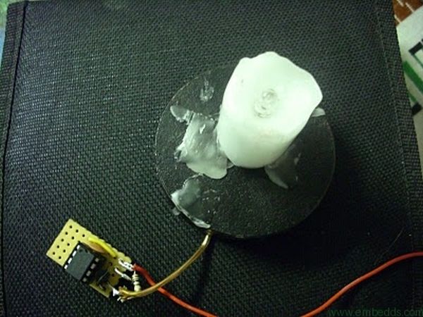
The aim of this project is to create a credible simulation of the light of a candle. Candle light is usually warm and waves slowly with random oscillations caused by the air flowing in the surrounding environment. Using a random number generator to modulate a light emiter like a LED or a light bulb it is possible to create a very credible effect.
Design
I tested both LEDs and small incandescent light bulbs and although LEDs require less current to produce the same amount of light, light bulbs tend to create a softer effect. In this circuit I'll use LEDs but nothing stops you from using light bulbs.
The brightness of the LED is digitally controlled using Pulse Width Modulation [1], generated by the micro-controller. The amount of brightness and its oscillations are governed by a random number generator based on a Linear Feedback Shift Register [2].
PWM or Pulse-width modulation of a signal or power source involves the modulation of its duty cycle, to control the amount of power sent to a load. This is because the average power delivered is proportional to the modulation duty cycle. With a sufficiently high modulation rate, passive electronic filters can be used to smooth the pulse train and recover an average analog waveform [1].
A linear feedback shift register (LFSR) is a shift register whose input bit is a linear function of its previous state. Applications of LFSRs include generating pseudo-random numbers, pseudo-noise sequences, fast digital counters, and whitening sequences. Both hardware and software implementations of LFSRs are common [2].
Circuit Implementation
I'll use both Microchip PICs 12F629 and 12F675 micro-controllers to develop the candle simulator. Each output pin of the micro-controler is limited to source or sink 25mA. This is enough to power a small 5mm LED but not a light bulb or even a more powerful 1W LED.
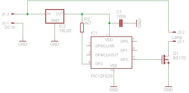
To power small light bulbs or more LEDs it is required to use a transistor like a bs170 n-channel mosfet, connected to the micro-controller. It will then provide the remaining power to the light bulbs or LEDs.
For more detail: Candle Simulator using PIC12F675 microcontroller
Quick Solutions to Questions related to Candle Simulator:
- How is the brightness of the LED controlled?
The brightness is digitally controlled using Pulse Width Modulation generated by the micro-controller. - What component creates the random oscillations?
A random number generator based on a Linear Feedback Shift Register governs the brightness and its oscillations. - Can light bulbs be used instead of LEDs?
Yes, although LEDs require less current, nothing stops you from using light bulbs. - Why is a transistor required in this circuit?
A transistor like the BS170 is needed to provide remaining power for light bulbs or more powerful LEDs that exceed the microcontroller's 25mA limit. - What limits the current output of the microcontroller pins?
Each output pin of the microcontroller is limited to source or sink 25mA. - Does PWM smooth the pulse train automatically?
No, with a sufficiently high modulation rate, passive electronic filters can be used to smooth the pulse train. - What determines the average power delivered to the load?
The average power delivered is proportional to the modulation duty cycle. - Which specific microcontrollers are recommended for this project?
The author uses both Microchip PICs 12F629 and 12F675 micro-controllers.
Related projects
PIC 12F675 Programmable 12V Battery Monitor
Being an active outdoor guy, I have a few different types of 12V lights and a variety of battery types. - For...
Audio, Sound & Radio · PIC12F675Audio CRO using PIC12F675 Microcontroller
This project is a miniature Audio CRO. For those not familiar with the abbreviation "CRO," it means "Cathode Ray Oscilloscope" and this...
Development Boards & Kits · PIC12F675DIY $1 PIC 12f675 JDM Programmer (Cheap and Easy)
Hi EveryBody i am Again Doing something. and it is with PIC's! Almost Everybody do not want a Big Arduino in their...
Home Automation & SecurityVoice Activated Power Sockets (Home Automation)
Yet another voice controlled home automation system! As shown in the picture, the system can control any electrical appliance, by turning ON...
Home Automation & SecurityHome Security System with GSM Using 8051 Microcontroller
Security is a big challenge everywhere because thefts are increasing day by day owing to the unsafe and insecure security systems in...
Home Automation & SecurityHome Automation and Security System using Microcontroller ATMEGA8 with Arduino Programming
Home automation and security systems have become very popular these days, today industrial automation techniques are widely adopted by luxurious homes and...

Ibrar Ayyub
I am an experienced technical writer holding a Master's degree in computer science from BZU Multan, Pakistan University. With a background spanning various industries, particularly in home automation and engineering, I have honed my skills in crafting clear and concise content. Proficient in leveraging infographics and diagrams, I strive to simplify complex concepts for readers. My strength lies in thorough...