Summary of PianoPIC
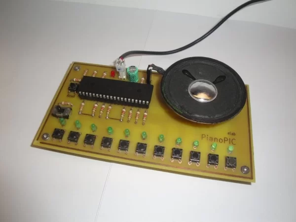
This project demonstrates a simple 8-bit style piano/synthesizer built around the PIC18F4550 microcontroller. It features eleven push buttons for musical notes, corresponding LED indicators, and a mode switch to toggle between playing and memory modes. The device generates square waves at specific frequencies to produce sound through a speaker. The PCB was fabricated using the toner transfer method on double-sided material, with components soldered after etching and drilling.
Parts used in the PianoPIC:
- PIC18F4550 micro-controller
- Push buttons (b1 to b11)
- Mode switch
- LED indicators (l1 to l11)
- Speaker
- Double sided PCB
- Laser printer
- Magnetic magazine paper
- Toner transfer materials
- Perchlorate solution
- Sponge
- Reset button (b0)
This little project is an example of a simple audio application using a PIC micro-controller.
We decided to use the PIC18F4550 micro-controller for memory purposes.
Using only digital inputs and outputs, we developed this simple piano/synthesizer with an 8 bit kind of style:
Inputs from b1 to b11 are the push buttons in the circuit while the mode input is the switch responsible for selecting the working mode. Outputs from l1 to l11 correspond to the LED indicators. Each LED is located right above its corresponding push button and it will light up when the respective musical note is played. The audio output is the pin that will connect to the speaker.
To make the circuit we used a double sided PCB. The circuit was printed in magazine paper using a laser printer, then it was transferred to the PCB using the toner transfer method. First on one side, then a few drills were made to align the designs on the other side. Then the PCB was put on an iron perchlorate solution to remove the copper from unprotected areas. To remove the toner we used a sponge under warm water. Then we made all the drills and placed all the components.
How it works:
In the Playing mode, when mode=0, the push buttons b1 to b11 correspond to “piano” keys:
b1 – A (440 Hz)
b2 – B (494 Hz)
b3 – C2 (261×2 Hz)
b4 – D2 (293×2 Hz)
b5 – E2 (329×2 Hz)
b6 – F2 (349×2 Hz
b7 – G2 (392×2 Hz)
b8 – A2 (440×2 Hz)
b9 – B2 (494×2 Hz)
b10 – C4 (261×4 Hz)
b11 – D4 (293×4 Hz)
We chose to use the second octave as main scale and then added two more musical notes up and down. It is also possible to reproduce sharps and flats by pressing two adjacent buttons.
When each button is pressed, a square wave is sent to the speaker with the respective frequency.
For instance, when b1 is pressed the note A must be played. So to create this sound, a square wave with 440Hz is sent to the audio output. To do that we know that the wave period is 1/440 = 2272 µs approximately, so the audio output is placed at high level during half this time (1136 µs) and then at low level during the other half.
if (b1)
{
audio=1;
delay_us(1136);
audio=0;
delay_us(1136);
}
Also, besides the sound, when the note A is reproduced, the l1 LED lights up.
In Memory mode each button is associated with a particular music that is played when the button is pressed.
Each music in memory is made with two vectors, one for frequencies or musical notes, and other for timings. These vectors are later read through the function Sound_Play(x,y) from the used compiler (mikroC).
At last, b0 is the reset button in our circuit.
Here’s the .hex file and the PCB layout: pianopic hex+pcb.zip
And the code as well: https://www.dropbox.com/s/nw5wv7xpbzb42je/code%20-%20pianopic.c
And that’s how to make another simple and fun application with a micro-controller.
Source: PianoPIC
- What microcontroller is used in this project?
The project uses the PIC18F4550 micro-controller chosen for its memory capabilities. - How are the musical notes generated?
A square wave is sent to the audio output pin at the specific frequency of the note when a button is pressed. - Can sharps and flats be played on this device?
Yes, it is possible to reproduce sharps and flats by pressing two adjacent buttons. - What happens when a button is pressed in Playing mode?
The respective musical note is played via the speaker and the corresponding LED above the button lights up. - How is the PCB manufactured in this project?
The circuit is printed on magazine paper with a laser printer and transferred to the PCB using the toner transfer method before etching. - What is the function of the mode input switch?
The switch selects the working mode between Playing mode and Memory mode. - How does the Memory mode work?
In Memory mode, each button plays a particular music stored as vectors for frequencies and timings. - Which button serves as the reset function?
Button b0 acts as the reset button in the circuit. - What compiler function is used to play sounds in Memory mode?
The Sound_Play(x,y) function from the mikroC compiler reads the frequency and timing vectors.