Summary of NU32: Introduction to the PIC32 using pic-microcontroller
The Microchip PIC32MX795F512L is a high-performance 32-bit microcontroller featuring an 80 MHz clock, 512K flash, and 128K RAM. Paired with the NU32 development board, it offers extensive peripherals including USB, Ethernet, ADCs, and serial interfaces. While faster than 8-bit variants, it requires surface-mount handling and 3.3V power. The project utilizes the NU32 board for easy breadboard prototyping via integrated voltage regulators and USB connectivity.
Parts used in the NU32 Development Project:
- PIC32MX795F512L microcontroller
- NU32 development board
- FT2232 dual serial-to-USB converter
- Two voltage regulators
- DC input jack
- USB connector
- USER push button
- RESET push button
- Two LEDs
- Standard prototyping breadboards
The Microchip PIC32 is a family of complex and powerful microcontrollers that can be purchased for less than $10 in quantities of one. This microcontroller offers many peripherals useful for mechatronics purposes, such as several channels for analog-to-digital conversion, digital I/O, synchronous and asynchronous serial communication, pulse width modulation, etc. For our purposes, the primary advantages of the 32-bit PICs over the 8-bit PICs we have used in the past are that they are faster (max clock rate of 80 MHz compared to 40 MHz), have more peripherals available, offer more program memory (flash) and data memory (RAM), and have significantly more computational horsepower due to the 32-bit address and data buses and single-cycle multiply for 32-bit math. The primary disadvantages are that they come only in surface mount packages, making them harder to work with for fast prototyping compared to the DIP (dual-inline packages) 8-bit PICs that can be plugged into a breadboard; and they must be powered by 2.3-3.6 V, unlike the 5 V of DIP 8-bit PICs and some DIP chips we would like to interface with. (Of course surface mount and lower operating voltages are vastly superior for commercial embedded products, and we will find ways to work around the disadvantages mentioned.)
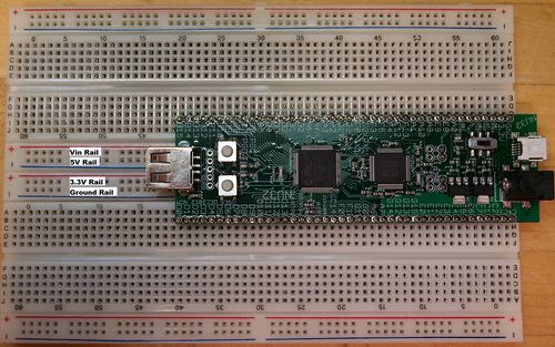
Particular numbers referenced on this page refer to the PIC32MX795F512L chip, which is the PIC32 used on the NU32 board. (You may wish to compare the capabilities of our PIC to others on the Microchip PIC32 parametric table.) The NU32 development board is shown on the right. The NU32 board was designed by Nick Marchuk to easily plug into two standard prototyping breadboards, allowing easy prototyping with the PIC32. The NU32 board also has two voltage regulators, a DC input jack, a USB connector, an FT2232 dual serial-to-USB converter, USER and RESET push buttons, and two LEDs to allow you to get up and running quickly with only the assembled NU32 board, a USB cable, a DC power supply, and a computer with free software (once a “bootloader” is installed on the PIC to allow you to program it from your computer). The NU32 board was created with inspiration from the UBW32 board and the NU32vX’s designed by NU graduate student Andy Long and Nick Marchuk.
The purpose of this page is to provide a brief overview of PIC32 and NU32 hardware. Microchip provides many reference manuals, data sheets, application notes, and sample software, and there are many other helpful web resources to take you further.
Also see
- NU32: What is in the NU32 Kit,
- NU32: Software to Install,
- NU32: Starting a New Project and Putting it on the NU32, and
- NU32: A Detailed Look at Programming the PIC32 on the NU32
pages for information specific to programming the NU32.
PIC32 Hardware Overview
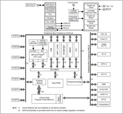
Our PIC32MX795F512L features a max clock frequency of 80 MHz, 512K program memory (flash), 128K data memory (RAM), multiple interrupt sources and handling routines, 16 10-bit analog-to-digital input lines (multiplexed to a single ADC), many digital I/O channels (with outputs that can be configured for open-drain), USB 2.0, Ethernet, five I2C and four SPI synchronous serial communication modules, six UARTs for RS-232 or RS-485 asynchronous serial communication, five 16-bit counter/timers (configurable to give two 32-bit timers), five pulse-width modulation outputs, and a number of pins that can generate interrupts based on external signals, among other features. This PIC has 100 pins.
Our PIC32MX795F512L features a max clock frequency of 80 MHz, 512K program memory (flash), 128K data memory (RAM), multiple interrupt sources and handling routines, 16 10-bit analog-to-digital input lines (multiplexed to a single ADC), many digital I/O channels (with outputs that can be configured for open-drain), USB 2.0, Ethernet, five I2C and four SPI synchronous serial communication modules, six UARTs for RS-232 or RS-485 asynchronous serial communication, five 16-bit counter/timers (configurable to give two 32-bit timers), five pulse-width modulation outputs, and a number of pins that can generate interrupts based on external signals, among other features. This PIC has 100 pins.
| Pin Label | Function |
|---|---|
| ANx (x=0-15) | analog-to-digital (ADC) inputs |
| AVDD, AVSS | positive supply and ground reference for ADC |
| BCLK1, BLCK2 | clocks for infrared (IrDA) comm encoding and decoding for 2 UARTs |
| CxIN-, CxIN+, CxOUT (x=1,2) | comparator negative and positive input and output |
| CLKI, CLKO | clock input and output (for particular clock modes) |
| CNx (x=0-21) | interrupts generated on change of these inputs |
| CVREF-, CVREF+, CVREFOUT | comparator reference voltage low and high inputs, output |
| D+, D- | USB communication lines |
| EMUCx, EMUDx (x=1,2) | used by an in-circuit emulator (ICE); not relevant in ME 333 |
| ENVREG | enable for on-chip voltage regulator that provides 1.8 V to internal core (set to VDD to enable on NU32) |
| ICx (x=1-5) | input capture pins for measuring frequencies and pulse widths |
| INTx (x=0-4) | pins used to generate external interrupts |
| MCLR (overbar) | master clear reset pin, resets PIC when low |
| OCx (x=1-5) | “output compare” pins, usually used to generate pulse trains (pulse width modulation) or individual pulses |
| OCFA, OCFB | fault protection for output compare pins; if a fault occurs, can be used to make OC outputs be high impedance (neither high nor low) |
| OSC1, OSC2 | crystal or resonator connections for different clock modes |
| PGCx, PGDx (x=1,2) | used with in-circuit debugger (ICD) |
| PMALL, PMALH | latch enable for parallel master port |
| PMAx (x=0-15) | parallel master port address |
| PMDx (x=0-15) | parallel master port data |
| PMENB, PMRD, PMWR | enable and read/write strobes for parallel master port |
| Rxy (x=A-G,y=0-15) | digital I/O pins |
| RTCC | real-time clock alarm output |
| SCLx, SDAx (x=1-5) | I2C serial clock and data input/output for I2C synchronous serial communication modules |
| SCKx, SDIx, SDOx (x=1-4) | serial clock, serial data in, out for SPI synchronous serial communication modules |
| SS1, SS2 (overbar) | slave select (active low) for SPI communication |
| TxCK (x=1-5) | input pins for counters when counting external pulses |
| TCK, TDI, TDO, TMS | used for JTAG debugging |
| TRCLK, TRDx (x=0-3) | used for instruction trace controller |
| UxCTS, UxRTS, UxRX, UxTX (x=1-6) | UART clear to send, request to send, receive input, and transmit output for UART modules |
| VDD | positive voltage supply for peripheral digital logic and I/O pins (3.3 V on NU32) |
| VDDCAP | capacitor filter for internal 1.8 V regulator when ENVREG enabled |
| VDDCORE | external 1.8 V supply when ENVREG disabled |
| VREF-, VREF+ | can be used as negative and positive limit for ADC |
| VSS | ground for logic and I/O |
| VBUS | monitors USB bus power |
| VUSB | power for USB transceiver |
| VBUSON | output to control supply for VBUS |
| USBID | USB on-the-go (OTG) detect |
For more detail: NU32: Introduction to the PIC32
- What are the primary advantages of the 32-bit PIC over 8-bit PIC?
The 32-bit PICs are faster with a max clock rate of 80 MHz, have more peripherals, offer more program and data memory, and possess significantly more computational horsepower. - Can the NU32 board be plugged into standard prototyping breadboards?
Yes, the NU32 board was designed by Nick Marchuk to easily plug into two standard prototyping breadboards for easy prototyping. - How many analog-to-digital input lines does the PIC32MX795F512L feature?
The chip features 16 10-bit analog-to-digital input lines which are multiplexed to a single ADC. - Does the NU32 board include a USB connector?
Yes, the NU32 board includes a USB connector along with an FT2232 dual serial-to-USB converter. - What voltage must the PIC32 be powered by compared to older DIP chips?
The PIC32 must be powered by 2.3-3.6 V, unlike the 5 V required by DIP 8-bit PICs. - How many UART modules are available on the PIC32MX795F512L?
The microcontroller has six UARTs for RS-232 or RS-485 asynchronous serial communication. - What components are needed to get up and running quickly with the NU32 board?
You need only the assembled NU32 board, a USB cable, a DC power supply, and a computer with free software after installing a bootloader. - Does the PIC32MX795F512L support Ethernet communication?
Yes, the chip includes USB 2.0 and Ethernet capabilities among its many features.