This loader connects the PC printer port and works with WinPic800. The loader gets DC supply from application board and provides +12V for high voltage programming mode. We can use it for programming many PIC chips easily.
Hardware Schematic
The In-circuit serial programming for PIC chips requires only three signals, i.e. a bi-directional DATA line (PGD), a synchronize clock (PGC), and a +12V Flash programming voltage (VPP). U1A is a tristate buffer for sending data stream. U1B is for clock stream. Both gates disconnect the signals, PGD and PGC from application board when VDD is turned off. The programming voltage +12V, is generated by DC-to-DC converter, U4 MC3406A. The hardware settings for WinPic800 is compatible with Propic2.
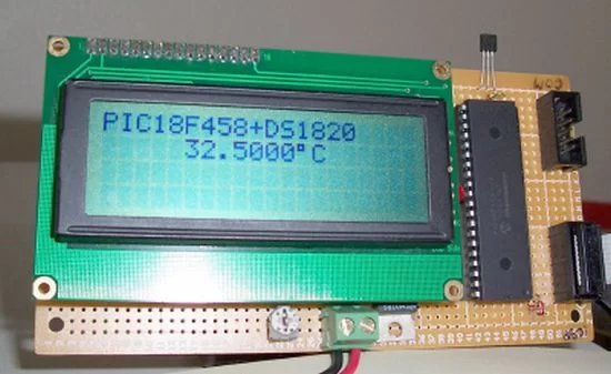
I built the test board with PIC18F458, DS1820 and 20×4 LCD display. Figure 7 shows hardware schematic of the test board. The test program displays temperature from -40C to +150C on LCD. Figure 8 shows code window of PIC18F458.
How to use WinPic800 with PIC loader.
For more detail: In-Circuit PIC Loader using PIC18F458 microcontroller

