Summary of USB Project :- USB Interface Board Using PIC18F4550
This low-cost USB interface board uses a PIC18F4550 microcontroller to control up to six LEDs and other devices like motors or relays via a C# application on Windows. Designed for beginners, it serves as an affordable alternative to expensive Arduino boards, offering a reliable way to interface with computers lacking parallel ports. The project includes firmware and software components, with detailed tutorials available for circuit construction, programming, driver installation, and bootloader setup.
Parts used in the USB Interface Board Using PIC18F4550:
- PIC18F4550 Microcontroller
- Six LEDs
- C# Software (4.0 .net framework)
- JDM Programmer
- WinPIC 800 Configuration Tool
- USB Port
- Laptop or Computer with Dot Net Framework
USB PROJECT: – USB INTERFACE BOARD USING PIC18F4550 Microcontroller CONTROL – 6 LEDS
C# software ( 4.0 .net framework)
PIC18F4550 Firmware – for 6 LED’s.
TUTORIAL FOR BEGINNERS
It’s a low cost USB interface Board that provides cool interface to your computer and it can be used to control various devices like DC Motor, Stepper motor ,Servo ,relay switch etc. with your laptop or any computer with a USB port and dot net framework installed. A small C# program communicates with the hardware to issue commands to set the pins of the Microcontroller. IN spite of LEDS u can use it as control signals for your project.
USB controlling is cooler than that of parallel port. Rather laptops now days don’t come with parallel port, so a USB port is a bit easy replacement. The Video will show you my USB Interface Board, see its working, I will post links for making your own Micro-controller board .
As arduino Boards are very costly and if are beginner with microcontroller then you really don’t wanna invest so much on a arduino board for the 1st time on microcontroller, rather if you make one mistake then you microcontroller is fumed (like exceeding Vmax of microcontroller).
The Video below will show you my USB DEMO INTERFACE DEVELOPMENT BOARD, see its working and in the end I will post links for making your own Microcontroller board.
I WILL PUT TUTORIAL TO MAKE THIS BOARD AT THE END PART.
BEGINNERS: Microcontroller projects are not like ordinary circuits (follow schematic and you are done) In case of Microcontroller board there are lots of steps. Microcontrollers are like Artificial Mind of a ROBOT.
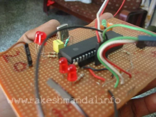
USB Demo Interface Development Board (PIC18F4550) : Tutorial for making this Board is Lengthy, so I will post the links for making this board.
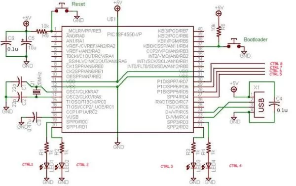
This a USB Demo Interface Device , that allows me to control 6 led’s, i have used a pic18f4550 microcontroller , i have found the schematics and diagrams on microchip.com to make it. I have modified it control 6 led’s , it is provides a cool interface to my computer using USB port and leds are controlled with clicks or pressing numpad buttons on my laptop.
It can be used to control various devices, like, Stepper Motor, servos, DC motor, Relay switches etc. etc. etc.
Download the firmware code ( for 6 – 8 leds) and C# application..
I Found this Nice Tutorial on a website while i was searching for some tutorial for making this board, i made a robotic arm based on this USB Interface Board, At beginning i thought of using Parallel Port but laptop don’t come with laptop , so using a USB port is a cool replacement of parallel or serial port with more better performance .This tutorial is actually not mine but i found it on a website and so sharing with all 🙂
UNFORTUNATELY FOR BEGINNERS THE DETAILED INFORMATION AND TUTORIAL STEP BY STEP CONSTRUCTION CAN BE VERY LENGTHY.
SO I AM GOING TO POST LINKS OF A DETAILED TUTORIAL
FOLLOW EACH STEPS ONE BY ONE… (for beginners )
STEP BY STEP
1- CIRCUIT CONSTRUCTION – http://www.rakeshmondal.info/pic18f4550-project-tutorial-part-1-USB
2- FIRST TIME PROGRAMMING – http://www.rakeshmondal.info/programming-a-microcontroller
3- Making of JDM PROGRAMMER TO LOAD CODE – http://www.rakeshmondal.info/How-to-make-a-JDM-Programmer
4- CONFIG WINPIC 800 with JDM – http://www.rakeshmondal.info/winpic800-config-for-JDM-Programmer
5- DRIVER INSTALLATION for PIC18F4550 board – http://www.rakeshmondal.info/pic18f4550-Driver-installation-tutorial
6- BOOTLOADING – http://www.rakeshmondal.info/BOOTLOADING-PIC18F4550-USB-BOARD
For more detail: USB Project :- USB Interface Board Using PIC18F4550
- What is the main purpose of this USB interface board?
The board provides a cool interface to your computer to control various devices like DC motors, stepper motors, servos, and relay switches. - Can I use this board instead of a parallel port?
Yes, using a USB port is a better replacement for parallel ports, especially since modern laptops do not come with them. - Why is this project recommended for beginners over Arduino?
Arduino boards are costly, and making mistakes can destroy the microcontroller, whereas this board is a lower-cost option for learning. - How many LEDs can be controlled by this specific setup?
This project is configured to control six LEDs, though the firmware code supports between six to eight LEDs. - What software is required to communicate with the hardware?
A small C# program built on the 4.0 .net framework is used to issue commands to set the pins of the microcontroller. - Is there a tutorial for building the JDM programmer?
Yes, there is a specific step-by-step guide available for making a JDM programmer to load code onto the board. - What steps are involved in getting the board ready for use?
Steps include circuit construction, first-time programming, making a JDM programmer, configuring WinPIC 800, installing drivers, and bootloading. - Where can I find the schematic diagrams for this project?
The schematics and diagrams were found on microchip.com to help make the board.