
Summary of Multimeter Clock
This article details the construction of a Multimeter Clock, where three analog multimeters display hours, minutes, and seconds driven by a 16F628A PIC microcontroller. The system uses tactile buttons for time adjustment and requires custom meter face scales. Construction involves assembling the circuit on a perfboard and building a multi-layer MDF housing using CNC routing techniques.
Parts used in the Multimeter Clock:
- Pre-programmed 16F628 chip
- 18 pin Chip Socket
- 2X3 inch perfboard Circuit Board
- 2 position Terminal Block
- 5X 1N4401 Diode
- 100uF 12V Filter Capacitor
- 47uF 5V Filter Capacitor
- .01uF 5V Decouple Capacitor
- 2X 22 pF Crystal Oscillator Capacitor
- LM7805 5V Regulator
- 20 mHz Crystal Oscillator
- 4X 4.7K Ohm Resistor
- 1X 1K Ohm Resistors
- 3X Tactile Button
- 2X 0.1 inch pin header (2 position)
- 2X 0.1 inch shorting jumper
- Blue LED
- 9 to 12 Volts DC Power Supply
- 3X Analog type Multimeters with 0.5mA setting
The Multimeter Clock consists of three multimeters, the first meter displays hours, the second displays minutes and the last displays seconds. A 16F628A PIC microcontroller keeps track of time and outputs a calculated current to each meter to display the current time.
Get your own Multimeter Clock Kit here.
See Multimeter Clock project page here.
Step 1: How it Works
The user enters the time by pressing three time adjust buttons. The first button increments the hours, the second button increments the minutes and the third button resets the seconds. Once the time has been entered the microcontroller will keep track of time from there. An interrupt fires every 10th of a second to increment a 10th second counter. Another routine checks to see if we have at least one full second of time, if we do the current time is incremented by a second.
The microcontroller has a separate output for each of the three meters. The meters are all in 0.5 DCmA mode, the negative lead of each meter is grounded and the positive leads are connected to a microcontroller output via a current limiting resistor. The resistor in this case is a 4.7K however this can be adjusted depending on the meter current scale available. Keep in mind that the PIC can deliver a maximum of 25mA to each meter so a meter with a lowest setting above 25mA would not work without additional circuitry.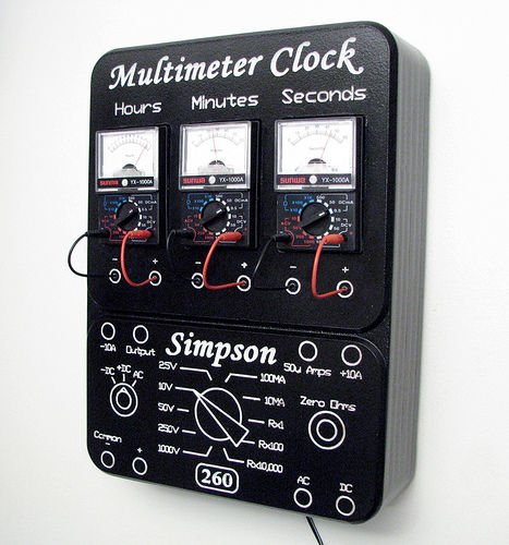
Step 2: Building the Clock Circuit
The clock kit shown below can be purchased here.
Since the clock controller is built onto a perf board you have lots of flexibility on layout. Construct the circuit according to the schematic diagram. The PIC Microcontroller will need to be programmed with the Multimeter Clock firmware using a PIC chip programmer. When powered up the blue LED will give you a visual indication that things are working, during the power up phase the LED will light steady and as soon as the clock is running it will flash on for one second and off for one second.
The firmware was written in PICBasic Pro so you will need that language if you wish to make changes to the existing functionality. There is still about 20% of the 2K PIC code space still available so there is lots of space for some hacking.
The meter faces of the multimeters will need to be updated to show time scales. I used a program called MeterBasic by Tonne Software. To make a new meter face all you need to do is enter the measurements of the meter face, the name for the meter and scale information. In the end you have a perfect matching scale for your meter. You can download the Hour, Minute and Second faces that I created for this clock here.
Here are the parts you will need.
1 X Pre-programmed 16F628 chip.
1 X 18 pin Chip Socket
1 X 2X3 inch perfboard Circuit Board
1 X 2 position Terminal Block
5X 1N4401 Diode
1 X 100uF 12V Filter Capacitor
1 X 47uF 5V Filter Capacitor
1 X .01uF 5V Decouple Capacitor
2 X 22 pF Crystal Oscillator Capacitor
1 X LM7805 5V Regulator
1 X 20 mHz Crystal Oscillator
4 X 4.7K Ohm Resistor
1 X 1K Ohm Resistors
3 X Tactile Button
2 X 0.1 inch pin header (2 position)
2 X 0.1 inch shorting jumper
1 X Blue LED
1 X 9 to 12 Volts DC Power Supply
3 X Analog type Multimeters, preferably with a 0.5mA setting
Step 3: Clock Schematic
Here is the schematic for the Multimeter Clock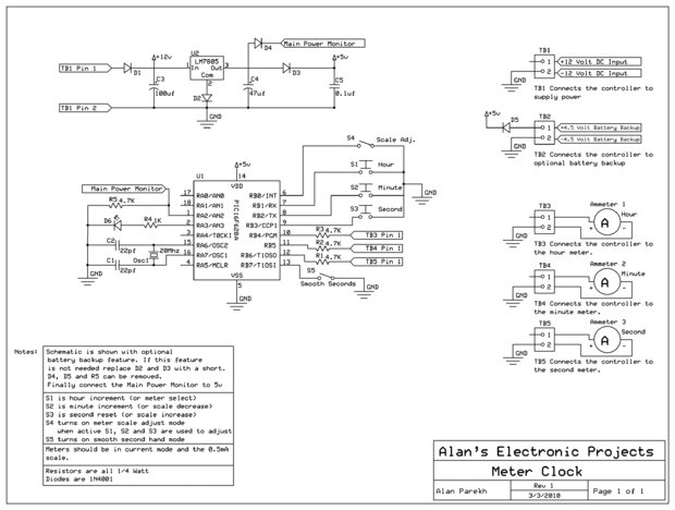
Step 4: Building the Clock Housing
To see more information about the V90 CNC machine that was used to build the housing have a look here.
The case was created using multiple layers of 1/2 inch MDF. There’s a front piece that has the actual Simpson 260 multimeter details v-carved into it. This is followed by 4 center spacer pieces and finally a back piece that has the hanging teardrop cutout.
The front piece was primed and painted with Krylon black paint before getting the details routed into it. All the other pieces were just routed in the CNC machine from raw MDF. I could have saved lots of wood if I built the sections from two pieces since the large center space in my design is wasted space but I decided to do it this way so that there will be no joints in the spacer pieces.
The black painted surface of the meter face was covered with contact paper then the details which will eventually be white were v-carved through the contact paper into the MDF. This provides a way of easily painting the fine white details using a spray gun.
For more detail: Multimeter Clock
- How does the user enter the time?
The user enters the time by pressing three time adjust buttons to increment hours, minutes, or reset seconds. - What determines the current output for each meter?
A calculated current from the PIC microcontroller is output to each meter based on the time. - Can any multimeter be used for this project?
No, the meters must preferably have a 0.5mA setting, and the lowest setting must not exceed 25mA. - What software was used to create the meter faces?
MeterBasic by Tonne Software was used to generate perfect matching scales for the meter faces. - How is the housing constructed?
The case is created using multiple layers of 1/2 inch MDF routed with a V90 CNC machine. - What programming language is required for the firmware?
The firmware was written in PICBasic Pro, which is needed to make changes to the functionality. - How does the blue LED indicate the clock status?
The LED lights steady during power-up and flashes on for one second then off for one second when running. - What is the interrupt frequency for the timekeeping routine?
An interrupt fires every 10th of a second to increment a 10th second counter. - How are the meter positive leads connected?
The positive leads are connected to a microcontroller output via a current limiting resistor.
