Summary of Connecting multiple tact switches on a single input pin of a microcontroller
This article demonstrates connecting four tact switches to a single ADC input pin on a PIC12F683 microcontroller using a voltage divider technique. By assigning unique pull-up resistor values to each switch, distinct voltage levels are generated upon pressing, allowing the microcontroller to identify the active switch via analog-to-digital conversion. The project also controls four LEDs individually through separate I/O pins, toggling them based on which switch is pressed.
Parts used in the Connecting Multiple Tact Switches Project:
- PIC12F683 microcontroller
- Four tact switches (SW1-SW4)
- Four LEDs (LED1-LED4)
- One common resistor (R = 470 Ω)
- Four individual pull-up resistors (R1'-R4')
- Analog input pin AN0
 Theory
The theory of connecting multiple switches on a single ADC input channel is very simple. One end of each switch is connected to the power supply voltage through an individual pull-up resistor, whereas the other end is grounded through a common resistor. When a switch is pressed, it creates a voltage divider network between the power supply and ground terminals. The value of the divided voltage can be made unique for all four switches by selecting different values of pull-up resistors. The voltage is then measured with the ADC to determine which switch has been pressed.
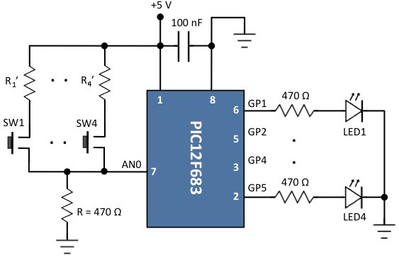
The circuit diagram shown below will probably give you a more clear picture of this technique. There are four switches (SW1-Sw4) connected to the AN0 input pin of the PIC12F683 microcontroller. Their one end is grounded through a common resistor R (=470 ?), whereas the other end is pulled high through different value resistors (R1‘-R4‘), giving rise to different values of the voltage divider output. The voltage drop across the resistor R is thus unique for each switch press and is measured through the AN0 ADC channel. When no switch is pressed, the AN0 pin is pulled low through R, and the ADC should ideally measure 0 V.
There are four LEDs (LED1-LED4) connected to pins GP1, GP2, GP4, and GP5 of the PIC12F683 microcontroller. They will be toggled ON and OFF through the four switches.
 Calculation of resistor R’
The resistors R1‘ – R4‘ determine the value of the voltage divider output for each switch press. We know that each resistor value must be different to create an unique analog voltage output across R for each switch. But how should we select their values? You should keep in mind that the resistors do have certain tolerance values and their values also change with temperature. Therefore, you should provide enough gap between any two consecutive values of the voltage divider output to avoid any conflict. The best practice would be to implement an evenly spaced values of the voltage divider for all 4 switches. Remember that when you press a switch, you should not expect a precise value of the analog voltage across the resistor R. It would fluctuate little bit within a certain range which is defined by the resistors’ tolerance values, temperature, contact resistance of the switches, and the stability of the power supply voltage. So, in order to identify the switch, what you are actually looking at is a range of voltage that the voltage divider output falls in.
- How many switches can be connected to a single input pin?
The tutorial demonstrates connecting four switches to one ADC input pin. - What technique allows multiple switches on one pin?
A voltage divider network with unique pull-up resistors for each switch creates distinct voltage levels. - Which microcontroller is used in this example?
The PIC12F683 microcontroller is used for this project. - How does the system determine which switch is pressed?
The ADC measures the unique voltage drop across the common resistor R to identify the pressed switch. - Why must pull-up resistor values be different?
Different values create unique analog voltage outputs for each switch to avoid conflicts. - What happens when no switch is pressed?
The AN0 pin is pulled low through resistor R, and the ADC ideally measures 0 V. - Which pins control the four LEDs?
The LEDs are connected to GP1, GP2, GP4, and GP5 of the microcontroller. - What factors cause voltage fluctuation?
Resistor tolerance, temperature changes, contact resistance, and power supply stability affect the voltage range.