Summary of Expanding the number of I/O lines using Microchip MCP23008 using pic microcontoller
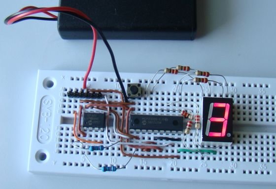
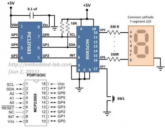
This tutorial demonstrates expanding the I/O capability of a PIC12F683 microcontroller using the MCP23008 I2C GPIO expander. The project connects a seven-segment LED display and a tactile switch to the expander, allowing the microcontroller to count switch presses and display the result.
Parts used in the Expanding I/O with MCP23008:
- PIC12F683 microcontroller
- MCP23008 I2C GPIO expander
- Seven segment LED display module
- Tact switch
 Theory
The MCP23008 an I2C slave device that provides 8-bit, general purpose, bi-directional I/O expansion for I2C bus. If you are not familiarized with I2C protocol, read my article on Inter-Integrated Circuit communication. MCP23008 supports 7-bit slave addressing, with the read/write bit filling out the control byte. The four most significant bits of the slave address are fixed (0100 for MCP23008) and the remaining three bits are user-defined hardware address bits (pins A2, A1 and A0). This allows us to connect up to eight MCP23008 devices on a common I2C bus. The control byte format for MCP23008 is shown below.
Control and configuration registers
The individual bits of the 8-bit GPIO port can be configured as input or output. The port pins can also be enabled for internal pull up resistor and interrupt-on-change. These operations are controlled through a set of configuration and control registers. The table below shows the list of these registers, their addresses and the power-on reset values.
These registers are described in the datasheet of MCP23008. I am summarizing them here. We will talk about configuring these registers for our specific purpose in the software section.
I/O Direction (IODIR): It controls the direction of the data I/O. When a bit is set, the corresponding pin becomes an input. When a bit is clear, the corresponding pin becomes an output.
Input Polarity (IPOL): It allows the user to configure the polarity on the corresponding GPIO port bits. If a bit is set, the corresponding GPIO register bit will store the inverted value on the pin.
Interrupt-on-change Control Register (GPINTEN): It controls the interrupt-on- change feature for each pin. If a bit is set, the corresponding pin is enabled for interrupt-on-change. The DEFVAL and INTCON registers must also be configured if any pins are enabled for interrupt-on-change.
 Interrupt Control (INTCON): It controls how the associated pin value is compared for the interrupt-on-change feature. If a bit is set, the corresponding I/O pin is compared against the associated bit in the DEFVAL register (described in next paragraph). If a bit value is clear, the corresponding I/O pin is compared against the previous value.
Default Comparison Value (DEFVAL): The default comparison value is configured in the DEFVAL register. If enabled (via GPINTEN and INTCON) to compare against the DEFVAL register, an opposite value on the associated pin will cause an interrupt to occur. For example, if GPINT6 (in GPINTEN), IOC6 (in INTCON) and DEF6 (in DEFVAL) bits are all set, then an interrupt will be generated when the GP6 I/O pin is pulled low. Of course, the GP6 pin direction should be defined as input.
For more detail: Expanding the number of I/O lines using Microchip MCP23008
- Why use an MCP23008 device?
To increase the I/O capability of a microcontroller when it has limited general purpose input and output ports. - How does the MCP23008 connect to other devices?
It uses a 2-wire serial interface known as the I2C bus. - What is the fixed address prefix for the MCP23008?
The four most significant bits of the slave address are fixed at 0100. - How many MCP23008 devices can be connected on one bus?
Up to eight devices can be connected because three address bits allow for unique hardware addressing. - How do you configure a pin as an input?
You set the corresponding bit in the IODIR register to define the pin direction as input. - What happens if a bit is set in the IPOL register?
The corresponding GPIO register bit will store the inverted value on the pin. - Which registers must be configured if interrupt-on-change is enabled?
The DEFVAL and INTCON registers must also be configured alongside GPINTEN. - When is an interrupt generated based on the DEFVAL register?
An interrupt occurs when the pin value is opposite to the configured default comparison value in DEFVAL.