This project started off being based on an Arduino UNO. And it worded ok, I found the software published on the internet. For example https://forum.arduino.cc/t/model-railroad-speedome…
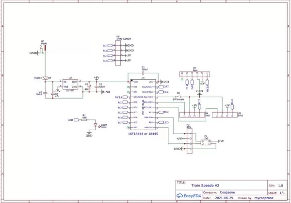
This is actually version 2 using a smaller PCB and PIC chip. It works in exactly the same way as V1.
I wanted to make the device smaller, neater and if possible to improve the software. With this version you can program different GUAGE (OO, HO, O, N, Z) using a press switch. You can select pre-set distances between the sensors (30cm, 50cm, 75cm or 100cm). With the 30cm version it’s easier to make a “portable” version to use on your layout in different locations etc.
Why choose a PIC? Well mainly I had some left over from another project! But also they are very cheap by comparison with an Arduino and not too difficult to program.
My other main motivation was to produce one of my first PCB designs for many years! I have a kit with all the parts ready to go, or a ready made version. If you want one look on Ebay for “Model train speedometer”
Supplies
Your going to need
A PCB for the project or strip board to suite. A Gerber file containing the PCB design can be found here along with the other files you need to program the PIC chip.
https://github.com/coopzone-dc/Train-Speedo-V2-fil…
A PIC 16F18445 (it has been tested on other chips in the same series, they all worked ok. Make sure it’s pin compatible with the PCB design if you use a PCB.)
Some method of programming the PIC chip. I used two methods both work ok.
1 Was the official SNAP debugger from microchip,
2 Was an Arduino project, https://github.com/jaromir-sukuba/a-p-prog
2x Infrared sensor boards (sold mainly as Arduino collision detectors on Ebay).
LED display, either a re-cycled TM1651 display from a Gotek Drive, many on Ebay – where people have upgraded these devices and have left over displays. Or you can use the 4 digit TM1637 normally sold as 4digit Arduino Display. Only the first 3 digits are used in this project, the 4th remains blank.
SPDP pcb mounted switch (only required if you want to change the GUAGE/Sensor Distance used to calculate the speed)
Resistor 1k 1/4 watt OPTIONAL, not used yet but for future expansion.
LED 3mm any colour OPTIONAL, not used yet but for future expansion.
2.54mm headers, to enable the use of Dupont connectors, you can just solder the wires in place if you prefer.
A Standard DC 2.1mm x 5.5mm Power Socket
1n4002 diode.
LM1117 5.0v regulator, You can use the 3.3v but it will not work with the add-on Hall effect sensors very well.
2x 100uf – 47uf 25v electrolytic capacitors, exact value not critical.
3x 100nf 50v ceramic capacitors.
Step 1: Assemble the Board
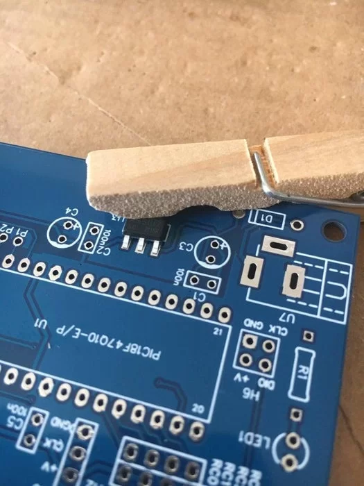
1, Starting with Voltage regulator, this is the only SMD (surface mount device), the good news is it’s quite a large device and is a very easy to solder. As with most SMD parts the trick is having three hands, one to hold the part in place, one for the solder and the last for the soldering iron. What you don’t have three hands? No problem! I suggest you use either a clothes peg to hold it or just some sticky tape to hold it in place. The photo above is from a slightly different board, but it’s the same idea.
2, Next the resistor R1, it’s a normal through hole device, like all the others. Solder in place and trim the leads.
3, I suggest the LED next. Make sure you get it the right way round. The Short lead (K) goes in the hole furthest away from the resistor.
4, Next the IN4002, D1, diode. Make sure the K (white line matches the PCB).
5, Now the capacitors, the 100nf (104) can go either way round. But the electrolytic ones have a negative and positive side, marked on the PCB as + for positive side.
6, Next the push button switch, make sure it’s flush with the PCB before you solder the leads. You may need to wiggle it a bit to achieve this.
7, Next the headers for the sensors, display and ICSP. I recommend a touch of solder on one pin to hold the header in place, not enough to be a complete the joint it only needs to stop the header falling out of place. Then re-heat this solder and adjust the position slightly to make sure the pins are vertical. It’s a bit fiddly. Once you get the pins vertical solder the remaining pins and finally add a very small amount of solder to the pin you used to align the header with – this prevents it being a dry joint where it was re-heated. As at alternative you can use the trusty clothes peg (not tape it melts!) to hold the pins in place.
8, Now it’s the Power connector, again a straight forward through-hole device.
9, Finally the 20-pin socket. Either use the “hold with a little solder” or the “clothes peg” to keep it in place while you solder it.
Step 2: Initial Tests
You should first do a visual check to make sure you have no shorts or dry joints on your PCB. Check the orientation of capacitors / led / diode etc.
Assuming it all looks good. Check the power is correct BEFORE you put the PIC chip into the board.
Check:
Voltage across C3 (47-100uf) it should be the same as your PSU (between 7v-14v).
Voltage across C4 (another 47-100uf) if should be 5.0 volts.
Voltage from pin 1 and pin 20 on the IC socket, again it should be 5.0 volts
Voltage on pins 2/3 on the header ICSP, again 5.0 volts.
You can also check other 5v pins (sensor connectors and display connector). Just to be sure.
Time to power off and insert the PIC chip. Be carful 20 pin devices can be tricky to get into sockets.
Power on and check a few voltages again. If it’s the same as above (C3 may drop a little) then carry on to the next step. if the voltages are wrong, ie less than 5v, power off and double check the PIC is inserted correctly
Next step program the PIC.
Step 3: Program Your PIC Chip
Download the .hex file for your PIC chip from (This version is for the PIC16F18445.)
https://github.com/coopzone-dc/Train-Speedo-V2-fil…
Or you can download a zipped up project for the Microchip X ide (version 4.45 and above) from the same GitHub site. If you decide to compile the project yourself (the exact workings of microchip’s X ide are beyond this article) export the .HEX file to a known location on your computer.
If you download the .HEX file ready compiled, save it to a known location on your computer.
I’m only going to describe the Arduino method of programming the PIC chip here, if your using SNAP or PICKIT I assume you already know what to do.
Using a-p-prog
Step 1 Download the software from https://github.com/jaromir-sukuba/a-p-prog. On the project page click the (Green “Code” icon, choose to download as a zip file.) Save the file on your computer.
Step 2 Unzip the downloaded file to an easy to find directory (I normally suggest something like c:\prog, this makes it easy to use the command prompt later). It’s probably a good idea to put a copy of the HEX file in the same directory as the a-p-prog
Step 3 Assuming you have already got a working Arduino setup on your computer, you can now compile the sketch found in the “fw/pp” directory called pp.ino. Upload this to your Arduino board ready for use.
Step 4 Find out what serial port your Arduino connects to on your computer on, it’s shown in the Arduino-IDE or from Hardware settings in control panel. In the example shown on the authors Github site it’s COM30
Step 5 You should read through the Github site and get familiar with the process used.
Connecting the PIC
At this stage only power the PCB using the Arduino, do not connect any other power source to it. During the initial wiring leave the Arduino unplugged.
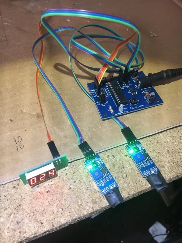
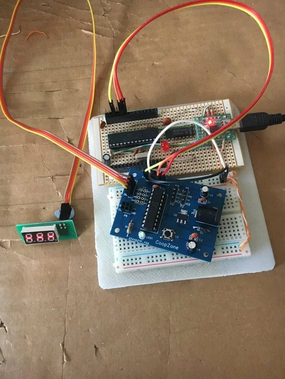
The above pictures show my “home-made” Arduino connected to the board, as described bellow. Any Arduino uno etc can be used. See the documents of Github mentioned above.
The other picture is a screen shot of my linux machine running the commands below, it works on windows just the same, but with different comm port names. Wiring connections are made using DUPONT male-female cables connect the Arduino to the PCB 6 pin header H2 ICSP like this:
Arduino     PCB

GND          3

5V           2

A3           1

A1           4

A0           5

6 not connected.
Double check the wires above, it’s a bit of a rats nest so be careful! Plug the Arduinio USB cable into your PC. The Arduino should start as normal. Open a command prompt and change directory to the directory containing the PPP.EXE program (if you used c:\prog, it will be cd c:\prog\sw)
Running the pp3 program
You can now test the connection to the PIC, with:
pp3.exe -c COM30 -s 1700 -p -n -t 16F18445
Note the COM30 port is the one you found for your Arduino board, probably not COM30.
You should see something indicating the com port is being opened. Then the the device ID of the PIC chip 30d0 will display.
If you get an error for the com port check you have the right one! If the device id is returned as 0000 then you need to check your wiring is ok.
If all is well you can program the chip with this command (don’t forget the HEX file has to be in the same directory and you need to use the correct com port)
pp3.exe -c COM30 -s 1700 -t 16F18445 hexfile.HEX
It should complete without error. You’re done! Further information can be found on the Github website.
Step 4: The Sensors
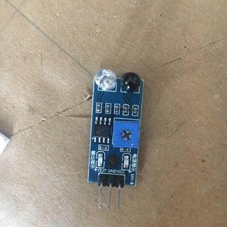
These are pre-made infra-red sensors made for Arduino experiments, very common on the likes of Ebay etc.
They have three pins on them:
1 VCC
2 GND
3 OUT
These connect to the PCB, one sensor on each of U4 and U5, like this:
Sensor	PCB
GND	3 GND
VCC	2 +V
OUT	1 S
Modify the sensors
I strongly recommend you fit a small piece of stiff card between the LED and IR sensor, as shown above. Use some heat shrink tubing to reduce the effect of ambient light on the sensor. By doing this you can increase the reliability and range of the sensor. I also (optionally) bent the IR/LED over at 90 degrees, for me this made positioning them easier. See pictures above.
Connections
You can use ready made cables for these or you can make your own using dupont headers and female connectors. Unless you need to detach the cables from the sensor end it’s just as easy to solder the wires directly on the board, use some heat shrink tubing to give the wires more strength and prevents shorts.
You can do the same on the PCB end, especially if you are going to mount it “under your layout” and not in a box.
I used 10 way ribbon cable, split down into 3way+3way+4way (2 sensors and 1 LED display). Try to keep the lengths as short as possible, it should be fine up to 3 metres (mine is using 1.5M + 2.5M + 0.5M for the first, second sensors and then the display).
When you have positioned the sensors, you can use various methods to fix them – anything from double sided sticky pads to small amounts of glue on the corners. They have to be close to the track (aprox 2-3 cm) and in a position that the train will be the only thing to reflect the light as it passes. For example inside the scenery at the exit to a tunnel or at the start/end of a platform etc. You can even drill up under the track and position them so they are active through the gaps in the track.
If you are not going to leave the speedo permanently on the layout or you are using it to check different parts of the layout, then mount the sensors on a strip of wood at 30cm apart. You can then put this on the layout temporarily to measure the speed at different locations.
Adjust the sensors
To get reliable sensing of the train you need to adjust the sensitivity of each sensor. This is a simple task. Using a small screwdriver turn the preset resistor on the sensor until the “OUT” Led turns on, then back off the preset until it goes out. By careful adjustment you should be able to get the sensor to trigger OK at a distance of up to 5cm or so. HOWEVER be aware that ambient light will effect this and can cause false triggering, it’s better to go for the minimum required setting for your layout – most likely around 2-3cm.
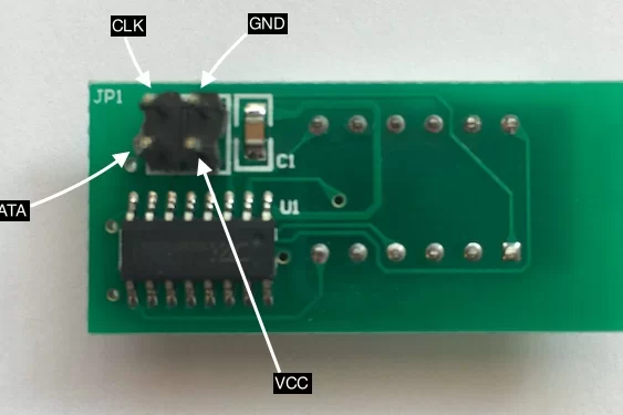
Step 5: Connecting the Display
Before connecting the display, power off.
You can use either a common 4-digit display designed to work with Arduino projects (available from Ebay etc) or a re-used display from a Gotek Disk drive (again from Ebay etc). The 4-digit display will only use the first 3 digits. I prefer the re-cycled Gotek LED display because it’s up-cycling and that helps the environment.
Unlike the sensors, because of the small 4 pin square connector on the LED display, I suggest you use either ready made dupont cables or make one. The pins connect like this:
Display		PCB
GND		1 GND
CLK		2 CLK
VCC		3 +V
DIO		4 DIO
Use the picture above to identify the pins on the back of the display.
Test the Display
This time when you power on you should see two numbers flash up (76,100) then the display will show “—“. This is the ready display (the first two number are current scale and distance between sensors) You should be able to press the on-board switch to go though 0,1,2 starting at 1. the screen will show =0,=1,=2 each time you press the switch ( you have about 5 seconds between presses to choose a menu, then the options in the menu will display). Finish on =0 witch will just exit and not make any changes. More on the menu later.
Step 6: The Menu Options
With everything connected, your ready to check the menu options. For most people the defaults are probably ok.
The options you choose in these menus are stored in EEPROM, so once selected you don’t need to change them again even after a power off.
Options are chosen using a single button.
The button auto selects the sub-menu when you stop pressing it for more than 5 seconds. Each time the button is pressed the sub-menu rotates in a round-robin sequence.
When you reach the sub-menu you need just wait a few seconds and it will be selected.
When you are selecting values in the sub-menu the button moves, round-robin through the values, leaving it on a value for more that 5 seconds auto selects that value.
The last value shown on the display will be saved in EEPROM and used from then on. This value will be used even after a power off.
The sub menu’s are:
0 - Exit and do nothing.
1 - Select the Scale to use
	076 - is 76:1 OO
	087 - is 87:1 HO
	048 - is 48:1 O
	148 - is 148:1 N
	220 - is 220:1 Z
2 - Selects the distance to use between the sensors
	30 - 30cm gap between sensors
	50 - 50cm gap between sensors
	75 - 75cm gap between sensors
	100 - 100cm gap between sensors
Note: Choosing a larger gap will increase accuracy but is sometimes more difficult to use on a layout. Try to keep the 30cm gap for portable use (sensors on a movable piece of wood). If possible use 100cm.
Step 7: User Documentation
I put together a very brief “how to use it” guide See attached PDF above.
Stay safe and well, have fun!
Attachments
Source: Model Train Speedometer V2