
Summary of Making a digital capacitance meter using microcontroller
This article details a project to build a digital capacitance meter using a PIC16F628A microcontroller. The device measures capacitance between 1 nF and 99 ?F by timing how long it takes a capacitor to charge from 0V to half the supply voltage through a series resistor. The system utilizes internal analog comparators and a Timer2 module to calculate the elapsed time, which is then used to determine the capacitance value based on the known resistance.
Parts used in the Digital Capacitance Meter:
- PIC16F628A microcontroller
- Analog Comparator 2 module
- TIMER2 module
- Two 2.2K resistors (voltage divider)
- 330? resistor (discharge path)
- 22K resistor (charging path)
- Capacitor under test (Cx)
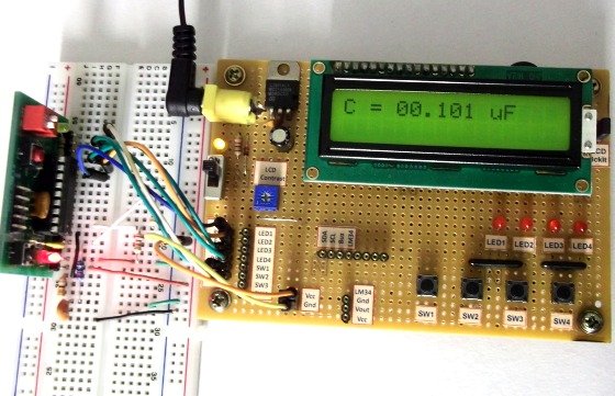
Capacitors are one of the most common passive electrical components that are extensively used in all kinds of electronic circuits. In this project, we will discuss a technique of building a digital capacitance meter using a PIC microcontroller. This project can measure capacitance values from 1 nF to 99 ?F, with a resolution of 1 nF. The technique is based on measuring the time elapsed when a capacitor is charged to a known voltage through a series resistor. The microcontroller used in this project is PIC16F628A.
Theory
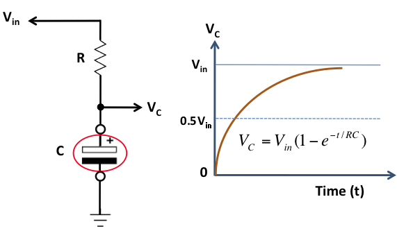
This capacitance meter is based on the principle of charging a capacitor through a series resistor. In a series RC circuit, as shown in the figure below, the voltage across the capacitor increases exponentially as it charges. Lets assume that initially the capacitor was fully discharged. When Vin is applied across the RC circuit, the capacitor starts charging and consequently, the voltage (Vc) across it increases from 0 towards Vin in an exponential way, as shown in the right side of the figure. The equation provided in the figure describes how the voltage across the capacitor changes with time. If we know the time that is required for the capacitor to charge up to a known voltage then we can solve this equation for C, knowing the value of R.
The idea of measuring the time elapsed when the capacitor is charged from 0 to a known voltage can be implemented with any microcontroller. Here, we are using the PIC16F628A microcontroller, which has two built-in analog comparators. In this project, we are using the Analog Comparator 2 and TIMER2 modules to determine the time required by the capacitor to charge from 0V to 0.5Vin. The positive and negative inputs of the Analog Comparator 2 are externally accessible through RA2 and RA1 pins of PIC16F628A, respectively. In the figure shown below, two 2.2K resistors creates a voltage divider that sets the positive input (RA2) of the comparator to half of the voltage applied to RA0 pin. The negative input (RA1) of the comparator goes to the positive end of the capacitor through a 330? resistor. The resistor is used to discharge the capacitor prior to its measurement by setting RA1 low. When a voltage is applied to the RA0 pin, the capacitor (Cx), initially fully discharged, is charged through a 22K resistor. When the RA0 pin is just set high (say around 5V), the output of the comparator is high as the positive input of the comparator is at higher voltage (about 2.5V) than the negative input, which is close to 0V as the capacitor is fully discharged. Now the capacitor starts charging through the series resistor (22K) and when the voltage across it exceeds half of the voltage at RA0 pin, the comparator output is flipped to low. The comparator interrupt flag (CMIF) is set whenever there is a change in the output value of the comparator. The Timer2 module is used to compute the time elapsed between when RA0 is set high and the comparator output goes low. This is the time required by the capacitor to charge from 0V to half of the supply voltage.
For more detail: Making a digital capacitance meter using microcontroller
- What is the primary function of this project?
To build a digital capacitance meter that measures values from 1 nF to 99 ?F. - How does the measurement technique work?
It measures the time elapsed when a capacitor charges to a known voltage through a series resistor. - Which microcontroller is used in this project?
The PIC16F628A microcontroller is used for the implementation. - What specific voltage level is used for charging measurement?
The system measures the time required for the capacitor to charge from 0V to half of the supply voltage. - Which pins are used for the Analog Comparator inputs?
RA2 is used for the positive input and RA1 for the negative input. - What is the role of the two 2.2K resistors?
They create a voltage divider that sets the positive input of the comparator to half the voltage applied to RA0. - How is the capacitor discharged before measurement?
A 330? resistor discharges the capacitor by setting RA1 low prior to measurement. - Which module computes the time elapsed during charging?
The Timer2 module computes the time between setting RA0 high and the comparator output going low.
