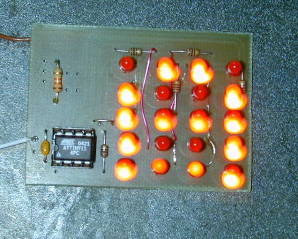
How to drive a lot of LEDs from a few microcontroller pins.
Using the fact that many microcontroller pins have three states (+V, GND, or
“high impedence”, you can drive N*(N-1) LEDs from N pins. So the little 8
pin microcontroller like a PIC12Fxxx or an ATtiny11 can drive 20 LEDs on
its five available output pins, and still have one pin left for some kind of input.
See also http://www.instructables.com/id/Charlieplexing-LEDs–The-theory/
Step 1
20 LEDs on 5 pins
the whole package) are attractively priced and ‘cute’, but the question
arrises as to how you can make the best use of those pins for common
applications such as driving LEDs.
A direct-connect approach to driving LEDs consumes one pin for each
LED. A traditional multiplexing scheme where rows of LED anodes are
driven by one set of N pins and each row’s common cathode is driven by
another set of M pins manages to light N*M LEDs with N+M pins.
However, on a processor with only 5 or fewer outputs (as is the case
with most 8-pin microcontrollers), this barely gets you any more
outputs than direct drive.
Step 2
Charlieplexing
Assuming the output pins are actually tri-state-able (active high,
active low, and high impedence (input)) it is also possible to share
the row and column drivers and control N*(N-1) LEDs with only N pins.
One pin is connected to common cathodes of a row of LEDs and driven
low, and the N-1 pins remaining are connected to the anodes and either
driven high to light that column, or left as inputs to leave the LED
off. Maxim calls this technique “Charlieplexing”, and describes it in
(1); Microchip also mentions this in their document (2) (and
implements in on the PICKit 1 board as well.)
(1) “Charlieplexing – Reduced Pin-Count LED Display Multiplexing”
http://www.maxim-ic.com/appnotes.cfm/appnote_number/1880
(2) “Tips ‘n Tricks 8-pin FLASH PIC Microcontrollers”
http://ww1.microchip.com/downloads/en/DeviceDoc/40040b.pdf
(3) Charlieplexing LEDs- The theory An Instructable by rgbphil
Step 3
Putting it to work.
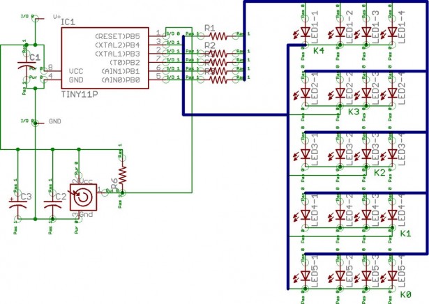
actually built and appears as the main page photo. I’m afraid the picture
of the schematic is pretty hopeless; you need Eagle to tell you which signals
are connected where.


