Summary of Low Cost 1 Wire Lcd for 8 Pin Micro Controllers [romanblack Shift1 System ]
Shift1 System is a low-cost solution that expands digital output pins using only one PIC microcontroller pin. It utilizes a serial-in parallel-out shift register (74HC595) and an RC network to distinguish between 0 and 1 bits based on pulse duration, eliminating the need for separate data and clock lines. The project includes a micro development board, MOSFETs, resistors, capacitors, and components for LCD contrast adjustment.
Parts used in the Shift1 System:
- 74hc595
- 1.5 k resistor
- 33 k resistor
- 0.1uf polyster capacitor
- 2.2nf non capacitor
- 220 ohm resistor
- 2n7000 mosfet
- 5K preset
- Button switch
- Pic12f675 microcontroller
Shift1 System is a cheap and simple way to get lots of digital output pins and only needs 1 PIC pin to drive it.

Step 1: How It Works – the Simple System
Normally, serial-in parallel-out shift register ICs can be set up for 2 pin operation;
DAT – data, is the next bit to be shifted in
CLK – clock pulse, on / edge the next bit is shifted in
This can be “cheated” to just use one pin and timed-length pulse. An RC network is used to provide a time delay for the DAT line to change. Very short pulses mean that a 1 bit is shifted in. With a long enough pulse the DAT voltage drops low enough so that a 0 bit is shifted in when the CLK line goes / again.
Step 2: Shift1 LATCHED System for Driving LCDs
reference link : http://www.romanblack.com/shift1.htm
Step 3: Circuit Diagram
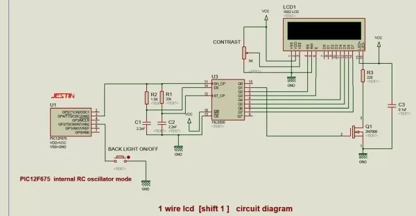
1, 74hc595 – 1
2, 1.5 k resistor -1
3, 33 k resistor – 1
4, 0.1uf polyster capacitor -1
5, 2.2nf non capacitor – 2
6, 220 ohm resistor -1
7, 2n7000 mosfet -1
8 ,5K preset – 1 ,for lcd contrast adjust
9, button switch – lcd back light ON/OFF [optional ]10, pic12f675
Step 4: Vero Board Assembling
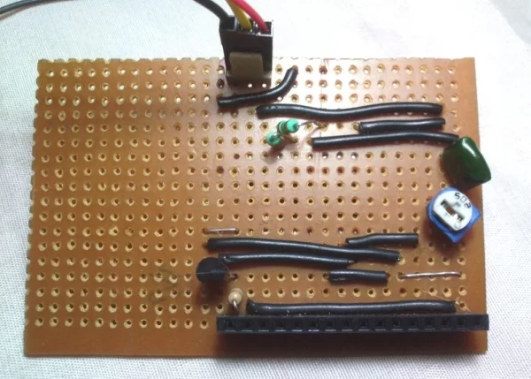
Step 5: Test Board – Pic12F675 Micro Development Board [3.0 Cm X 2.5 Cm Size]
pic12F675 micro development board
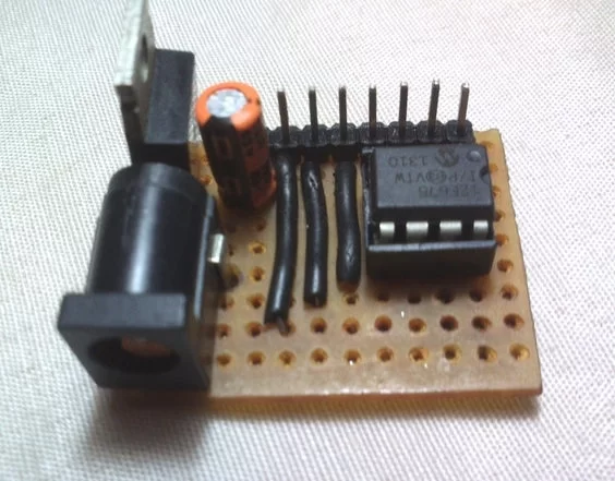
Step 6: Finished Circuit Board
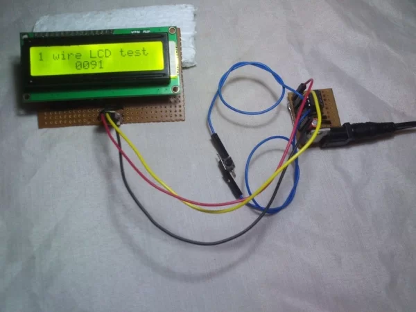
Step 7: Working Video
special thanks to roman black.
Source: Low Cost 1 Wire Lcd for 8 Pin Micro Controllers [romanblack Shift1 System ]
- How does the system work with only one pin?
An RC network provides a time delay so short pulses shift in a 1 bit while long pulses drop the voltage low enough to shift in a 0 bit. - What IC is used for serial-to-parallel conversion?
The project uses a 74hc595 shift register IC. - Which microcontroller is recommended for this project?
The Pic12f675 microcontroller is used as the driver. - Can this system drive an LCD display?
Yes, the article describes a latched version specifically designed for driving LCDs. - What component adjusts the LCD contrast?
A 5K preset is used for LCD contrast adjustment. - Is there an option to control the LCD backlight?
Yes, a button switch can be added for optional LCD backlight ON/OFF control. - Does the design require two wires for operation?
No, it is designed to use just one pin by cheating the standard two-pin setup.