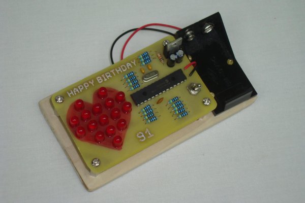
With my Grandma’s birthday fast approaching I wanted to put something together that was not too complicated but still sweet enough to make for a cool widget gift. Since fading LEDs never seem to go out of style and grandmas always love to see a heart, putting two and two together here was a no-brainer.
The concept for this small birthday present was to create a small heart shape with red LEDs and then to draw a heart shape underneath it on the PCB as a backdrop. Then a microcontroller was added to control the LEDs for both fade and pattern control. Controlling LEDs via PWM allows us to save precious battery life and control the exact brightness of each specific LED.
Purpose & Overview Of This Project
The goal of this project is to create a PCB with some LEDs connected to a microcontroller. The LEDs should be individually controlled by the microcontroller so much so that each LED can be set to a different brightness level individually. With this control in place 6 modes of operation should be programmed:
- LEDs ‘around the heart’
- A total heart fade-in-out
- A wave-like fade bottom to top
- A wave-like fade right to left
- A single row fade in and out
- A single column fade in and out.
To achieve this goal, we will use 16 5mm Red LEDs for the heart and a PIC 18F252 microcontroller for the processing. Some other components will be needed as well, so please continue on to see the parts list.
PICKit2 PIC Programmer
7805 +5v Regulator
16x Red 5mm LEDs
16x 100Ω Resistors
10kΩ Resistor
20 MHz Crystal
Toggle Switch
2x 1uF Capacitors
0.1uF Capacitors
2x 15pF Capacitors (22pF is ok)
+9v Battery Holder
4x Stand-Offs
Balsa Wood Mount
PC Board
Ferric Chloride (Etchant)
Glossy Paper
Laser Printer
Solder
Soldering Iron
Parts List Details
There are a lot of parts to this project. Too many to describe them all in detail, however below I have given some further information on the main parts that we’ll be using.
PIC 18F252
This is a small microcontroller (processor + memory). It wil be incharge of controller each LED individually, which is the main goal of this project. PICs are very versatile, in fact this PIC 18F252 has a lot more functionality built into it than just technology for fading LEDs. It’s a shame we’re not using more of the hardware on this bad boy.
PICKit2 PIC Programmer
In order to get your program (firmware) onto the PIC, you will need a programmer. The PICKit2 is a programmer/debugger and one of the most popular tools for programming PICs.
16x Red 5mm LEDs
16 LEDs will be used to create the heart shape. This isn’t very many LEDs and so the heart will likely look ‘pixelized’ but I’m okay with that, you can use more if you want to.
20 MHz Crystal
The crystal used for this project doesn’t matter so much. 4 MHz, 1 MHz or 40 MHz could have been used. 20 MHz is just the first crystal I found when rooting around my tool kit.
PC Board and Ferric Chloride (Etchant)
Since I want to make a PCB, we’ll need some raw PC Board (copper on both sides) and some ferric chloride to etch away the unwanted copper. We’ll use the toner transfer method to make the PCB.
Schematic Overview
The schematic for this project is not too terrible, it’s mostly connecting the LEDs to current limiting resistors and then to the PIC. Although it might seem that I arbitrarily chose connections for each LED, there’s reason for each LED # to connect where it is: it makes the layout process easier for us.
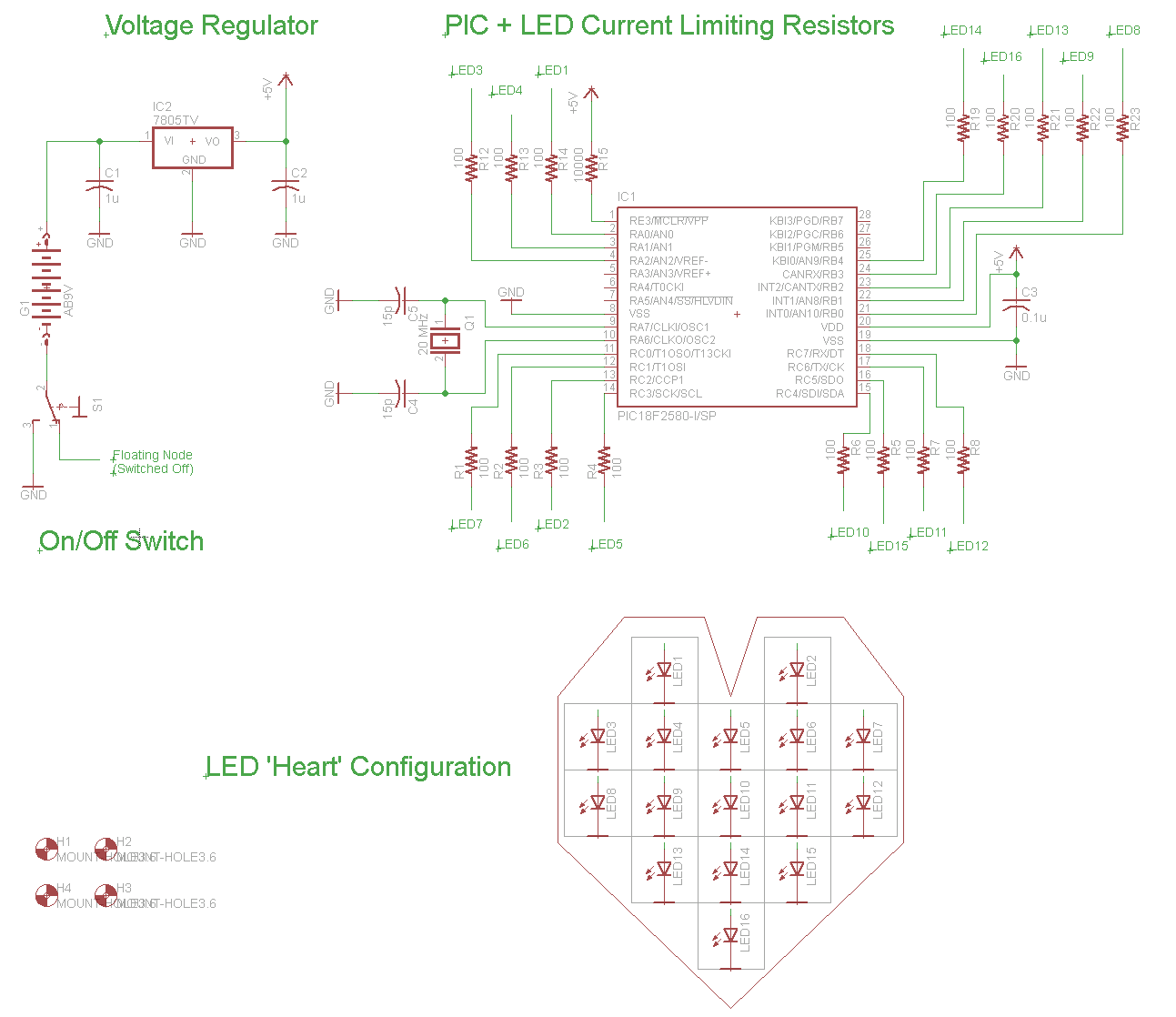
Schematic Specifics
+5v Power Regulator and On/Off Toggle Switch
A 7805 Linear Regulator will be used to regulate the +9v battery down to +5v that the PIC needs to operate. The toggle switch connects the entire circuit to ground allowing current to flow through the circuit, thus turning it on or off.
PIC Microcontroller + 100Ω Resistors
The PIC’s general purpose outputs on PORTA, PORTB and PORTC will be used to connect to each individual LED thus giving us maximum control over each LED when programming to tell it what to do. 100Ω current limiting resistors are placed between the general purpose I/O port and the LED so that we don’t burn out the PIC or the LED by allowing too much current to flow through the microcontroller’s pin or the LED.
For more detail: LED Heart PWM Fading using PIC18F252