Summary of An AVR microcontroller based Ethernet device
The article introduces the ENC28J60 Ethernet chip, highlighting its compact 28-pin design and SPI interface as a solution for microcontroller-based projects. It details a generic hardware setup using an AVR microcontroller to control a relay via UDP commands over Ethernet. The text provides circuit guidance, component lists including magnetics and filters, and discusses hardware updates from 2007 regarding diode orientation and clock signals.
Parts used in the AVR Microcontroller Based Ethernet Device:
- ENC28J60 Ethernet chip
- Atmega88 microcontroller
- Crystal oscillator
- Ethernet transformer (magnetics)
- RJ45 Magjack connector
- Ferrite bead filter coil (L1)
- Relay (6V or similar)
- Diode D1
- LM2937-33 voltage regulator
- Resistors (parallel and series options)
- Connector CONN3
Ethernet has traditionally been a quite complex interface. All Ethernet chips until today had 100 pins or more, where difficult to find in small quantities and difficult to use from a small microcontroller with little memory. Microchip has changed the world with their new ENC28J60 Ethernet chip!
The ENC28J60 is a small chip with 28 pins only and has a SPI interface which is easy to use from any microcontroller.
This opens a whole world of completely new applications. You can easily build small devices which can be spread all over the house and simply connected to ethernet.
You don’t need anymore a separate serial connection or other bus. Everything can be easily connected via Ethernet. Distance is no longer a limiting factor.
Even WIFI connectivity is possible because you can connect the devices to a wireless bridge.
All hardware components are available from shop.tuxgraphics.org. The software and circuit diagrams are available for free (GPL V2 license)
Introduction to the ENC28J60 Ethernet controller
The ENC28J60 from Microchip is a fantastic chip. It has Tx/Rx, MAC and PHY in one small chip. There are very few external parts. Basically just a crystal and an Ethernet transformer, aka magnetics. All this comes in an convenient 28-pin DIP package. Easy to solder and perfect for hobby applications.
The microcontroller can then control any hardware you like: You can attach some sensor (light, temperature), you can switch on an off something you can attach a LCD display, etc…
The Plan
In this first article we will build a generic hardware with lots of IO interfaces and analog to digital converter inputs. We will however only control a small relay to switch on or off something. In later articles we can then use the same hardware and do more complicated things.
The main purpose is to show here the circuit diagram and explain the software. We use a UDP application to send commands to the microcontroller. Those commands will then cause the microcontroller to switch on or off the relay.
It think it will be possible to even implement TCP. The current UDP software is less than 3k bytes and that is not even half of the memory on an Atmega88. TCP would then allow us to control the device via a web browser. I have however not tried it yet.
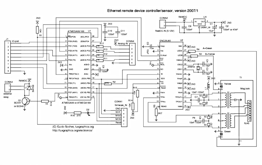
The circuit diagram
Here is the circuit diagram. Most of it is very straight forward and standard for the ENC28J60. The polarity of LED-B is important as it determines the duplex operation of the chip. Standard Half-duplex is what makes most sense for a device which will send and receive only rather little traffic.
A relay can be connected to connector CONN3. Note the diode D1. It is not useless and it is not the wrong way round in the circuit diagram even though it looks like that. It is there for those who plan to connect a small 6V relay on that output. It protects the whole circuit against the possibly very high voltages which can be induced by the coil of a relay.
If you use a relay with a large coil then you should also add a resistor in parallel to the relay (e.g 1K or 2.2K). The diodes have a finite response time and such a resistor will prevent the voltages to raise too fast before the diode cuts them.
If you plan use 9V raw-DC (or maybe more) in combination with a 6V relay on CONN3 then you can add a small resistor (e.g 33 Ohm, you have to experiment) in series to the relay to compensate for the higher voltages.
The connectors named “IO-ports” and “Analog-IN” are not used for now. They are meant for future functionality which will be described in later articles. We will only use CONN3 in this project.
Ethernet requires quite high currents because it can be used with rather long cables. The above circuit consumes about 200mA at 3.3V. The LM2937-33 needs therefore cooling if the supply voltage is more than 5V (on Raw-DC-In). A small piece of aluminium is normally enough.
Ethernet Magnetics and Filters
The ENC28J60 requires a transformer with a turn ratio of 1:1 certified for 10base-T. There are some very nice RJ45 connectors called “Magjack” which have already integrated magnetics and optionally integrated LEDs. In addition you need a small filter coil (L1 in the schematic). A 5mm ferrite bead with 5-7 turns of thin wire seems to work well.
Hardware updates 2007
As of quarter one 2007 I have updated the hardware with regards to the following points:
- The diode D1 was incorrectly connected against GND instead of Vdd. Interestingly nobody noticed that fault. The wrongly connected diode was protecting the transistor against negative voltages but not against voltage peaks induced by a relay coil. If you did however follow my recommendation and use an additional resistor in parallel to the coil then this one will keep already the current flowing through the coil after power disconnection and it seems to be enough to protect the circuit.

- The ENC28J60 has a clock output. I wanted to use it right from the start but there was a problem with interrupted clock signals at reset which caused sometimes the AVR to malfunction. I contacted microchip support about it but they did not seem to understand the problem. Maybe microchip PIC controllers are less sensitive to non continuous clock signals. I finally figured out that it works if I do not use both software and hardware reset during initialization of the chip. Now I use just reset via software and that works well. The ENC28J60 can supply a 12.5MHz clock signal. This gives a small speed increase over the 8MHz from the atmega88 internal clock. Atmel specifies that the atmega88 can handle 0-20MHz @ 4.5-5.5V and 0-10MHz @ 2.7-5.5V. This suggests that we should use max 10MHz but it can’t be a binary behavior starting suddenly at 2.7V. We can assume that it should be something between 10MHz and 20MHz. My tests show that 12.5MHz works stable and reliable at 3.3V.
If you did already build the previous circuit then don’t worry. I will keep any new software backward compatible with the old hardware. That is: the new hardware will not run with the old software but the old hardware will run with the new software. There is also no real need to modify or update your existing hardware. Never change a running system! For those who would like to look at the old circuit diagram from 2006 can find it in the download section.
For more detail: An AVR microcontroller based Ethernet device
- What makes the ENC28J60 suitable for small microcontrollers?
It is a small chip with only 28 pins and features an SPI interface that is easy to use. - Can this device connect to WIFI networks?
Yes, WIFI connectivity is possible by connecting the devices to a wireless bridge. - How does the circuit protect against relay coil voltage spikes?
A diode D1 protects the circuit, and adding a resistor in parallel prevents voltages from rising too fast before the diode cuts them. - What is the recommended power supply current consumption for this circuit?
The circuit consumes about 200mA at 3.3V, which may require cooling for the LM2937-33 if the input voltage exceeds 5V. - What type of transformer is required for the ENC28J60?
The chip requires a transformer with a turn ratio of 1:1 certified for 10base-T. - How can the system be controlled via a web browser?
Implementing TCP would allow control via a web browser, though the current software uses UDP. - Does the updated hardware work with old software?
No, the new hardware will not run with the old software, but the old hardware will run with the new software. - What clock signal frequency was found to work stable at 3.3V?
Tests showed that 12.5MHz works stable and reliable at 3.3V when supplied by the ENC28J60 clock output.