
Summary of LCD OSCILLOSCOPE CIRCUIT PROJECT PIC18F4520
This article describes a DIY oscilloscope project built around the PIC18F4520 microcontroller. It features a 128×64 LCD for display and includes PCB schematics, source code files (menu.c, glcd.c), and a bootloader hex program for installation. The project serves as an educational resource for electronics enthusiasts working with microcontrollers.
Parts used in the LCD Oscilloscope Circuit Project:
- PIC18F4520 microcontroller
- 128×64 LCD
- PCB schematics
- Source code files (menu.c, glcd.c)
- Bootloader hex program
Oscilloscope circuit PIC18F4520 microcontroller based on the indicators used for the 128×64 LCD PCB schematics and source code for the project given all menu.c, etc. glcd.c. in different projects such as files can be... Electronics Projects, LCD Oscilloscope Circuit Project PIC18F4520 “microchip projects, microcontroller projects, “
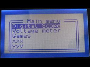
Oscilloscope circuit PIC18F4520 microcontroller based on the indicators used for the 128×64 LCD PCB schematics and source code for the project given all menu.c, etc. glcd.c. in different projects such as files can be useful also to install the bootloader hex program and the circuit shown in Diagram.
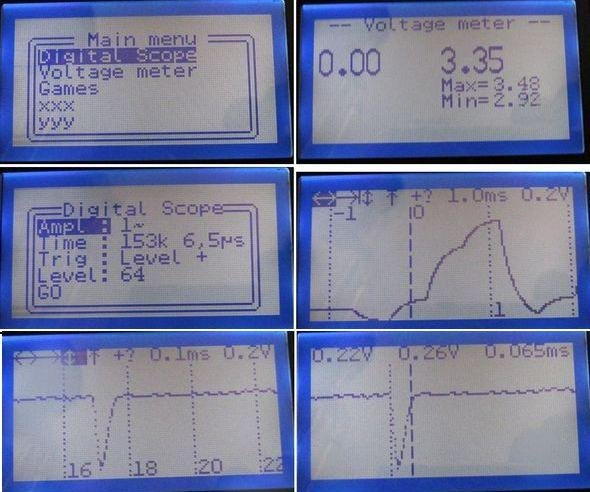
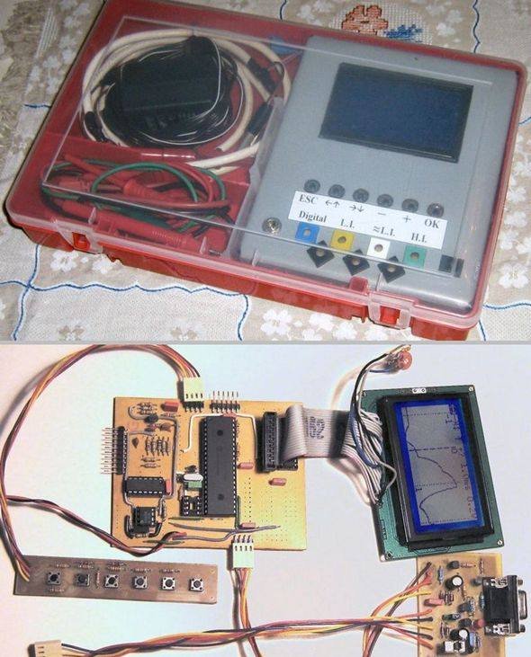
Source: LCD OSCILLOSCOPE CIRCUIT PROJECT PIC18F4520 alternative: lcd-oscilloscope-circuit-project-pic18f4520.rar alternative link3
- What microcontroller is used in this oscilloscope circuit?
The project uses the PIC18F4520 microcontroller. - What type of display does the circuit support?
The indicators are based on a 128×64 LCD. - Which source code files are provided for the project?
The available files include menu.c and glcd.c. - How can the bootloader be installed?
The circuit shown in the diagram allows for installing the bootloader hex program. - Are PCB schematics included in the project?
Yes, PCB schematics are provided for the indicators used in the project. - Can this project be useful for other electronics projects?
Yes, the files can be useful for different projects such as microchip projects and microcontroller projects. - Where can alternative links for the project files be found?
An alternative link named lcd-oscilloscope-circuit-project-pic18f4520.rar is mentioned.
