Description
HD44780 based LCD displays are very popular among hobbyists because they are cheap and they can display characters. Besides they are very easy to interface with microcontrollers and most of the present day high-level compilers have in-built library routines for them. Today, we will see how to interface an HD44780 based character LCD to a PIC16F688 microcontroller. The interface requires 6 I/O lines of the PIC16F688 microcontroller: 4 data lines and 2 control lines. A blinking test message, “Welcome to Embedded-Lab.com”, will be displayed on the LCD screen.
Required Theory
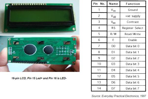
All HD44780 based character LCD displays are connected through 14 pins: 8 data pins (D0-D7), 3 control pins (RS, E, R/W), and three power lines (Vdd, Vss, Vee). Some LCDs have LED backlight feature that helps to read the data on the display during low illumination conditions. So they have two additional connections (LED+ and LED-), making altogether 16 pin. A 16-pin LCD module with its pin diagraam is shown below.
Control pins
The control pin RS determines if the data transfer between the LCD module and an external microcontroller are actual character data or command/status. When the microcontroller needs to send commands to LCD or to read the LCD status, it must be pulled low. Similarly, this must be pulled high if character data is to be sent to and from the LCD module.
The direction of data transfer is controlled by the R/W pin. If it is pulled Low, the commands or character data is written to the LCD module. And, when it is pulled high, the character data or status information from the LCD registers is read. Here, we will use one way data transfer, i.e., from microcontroller to LCD module, so the R/W pin will be grounded permanently.
The enable pin (E) initiates the actual data transfer. When writing to the LCD display, the data is transferred only on the high to low transition of the E pin.
Power supply pins
Although most of the LCD module data sheets recommend +5V d.c. supply for operation, some LCDs may work well for a wider range (3.0 to 5.5 V). The Vdd pin should be connected to the positive power supply and Vss to ground. Pin 3 is Vee, which is used to adjust the contrast of the display. In most of the cases, this pin is connected to a voltage between 0 and 2V by using a preset potentiometer.
Data pins
Pins 7 to 14 are data lines (D0-D7). Data transfer to and from the display can be achieved either in 8-bit or 4-bit mode. The 8-bit mode uses all eight data lines to transfer a byte, whereas, in a 4-bit mode, a byte is transferred as two 4-bit nibbles. In the later case, only the upper 4 data lines (D4-D7) are used. This technique is beneficial as this saves 4 input/output pins of microcontroller. We will use the 4-bit mode.
For further details on LCDs, I recommend to read these two articles first from Everyday Practical Electronics magazine : How to use intelligent LCDs Part 1, and Part 2.
Circuit Diagram
Data transfer between the MCU and the LCD module will occur in the 4-bit mode. The R/W pin (5) of the LCD module is permanently grounded as there won’t be any data read from the LCD module. RC0-RC3 serves the 4-bit data lines (D4-D7, pins 11-14) of the LCD module. Control lines, RS and E, are connected to RC4 and RC5. Thus, altogether 6 I/O pins of the PIC16F688 microcontrollers are used by the LCD module. The contrast adjustment is done with a 5K potentiometer as shown below. If your LCD module has backlight LED, use a 68Ω resistance in series with the pin 15 or 16 to limit the current through the LED. The detail of the circuit diagram is shown below.
For more detail: Lab 4: Interfacing a character LCD using PIC16F688

